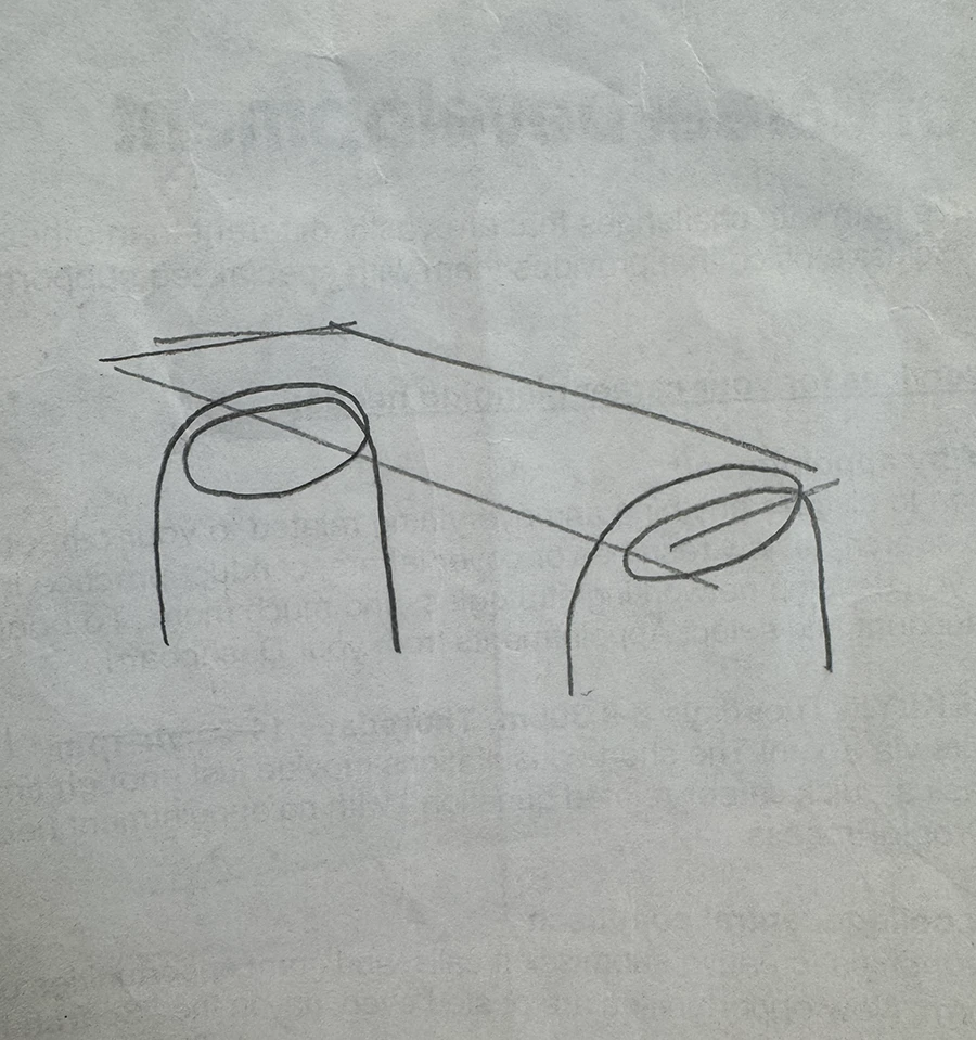
These last two weeks of the course were focused on the final assignment: fabricating and object that uses two materials and fasteners. For this one, I wanted to experiment with bent metal tubes to create legs for a wooden table.
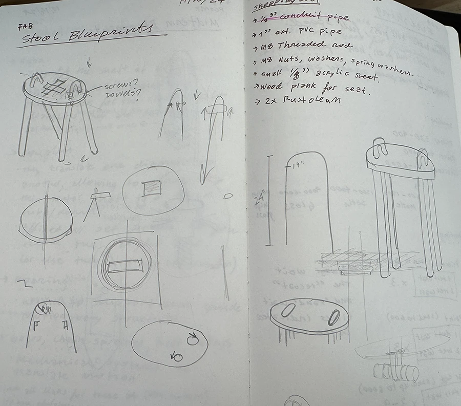
This was the initial design for the table. After talking to Phil and analyzing the possibilities, it was evident that these bends would be very complicated to make.This was a different idea, making it a stool instead of a table. In order to get the legs in with that angle, I would have had to make some angled holes and split the top in half, which was going to be a very precise operation.
After these sketches and discussing the idea with Phil and Niko, I decided to do a blend of the ideas, to simplify the fabrication process a bit.
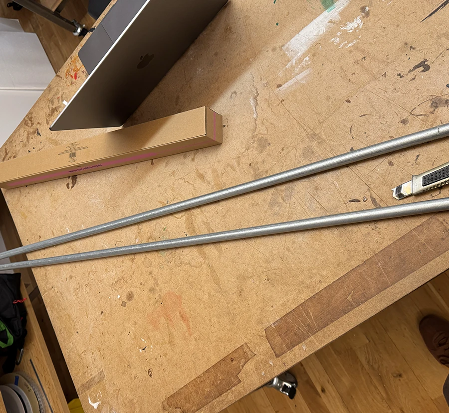
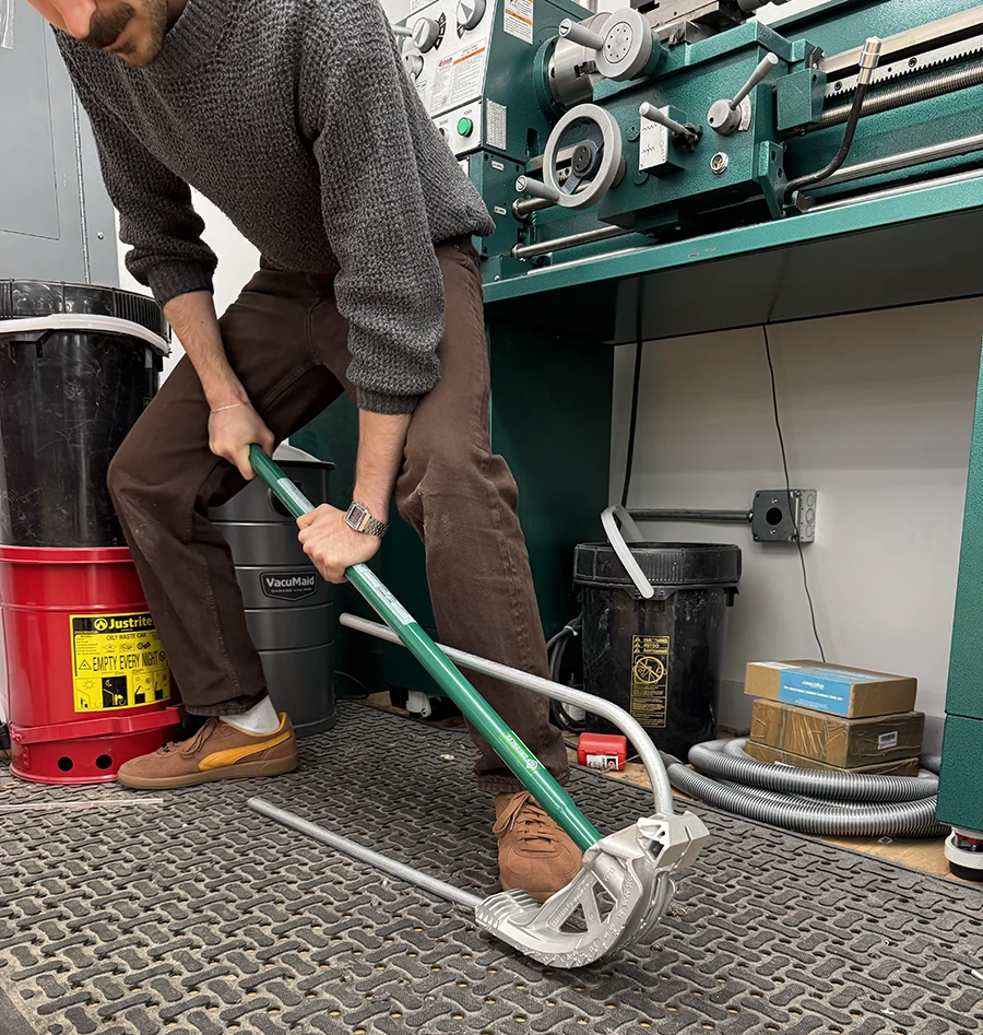
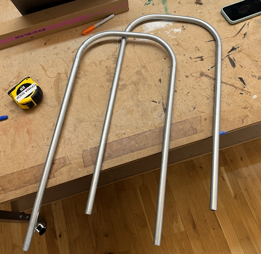
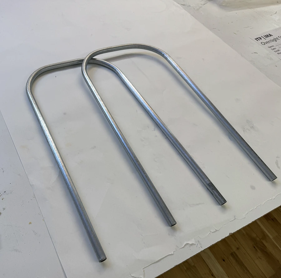
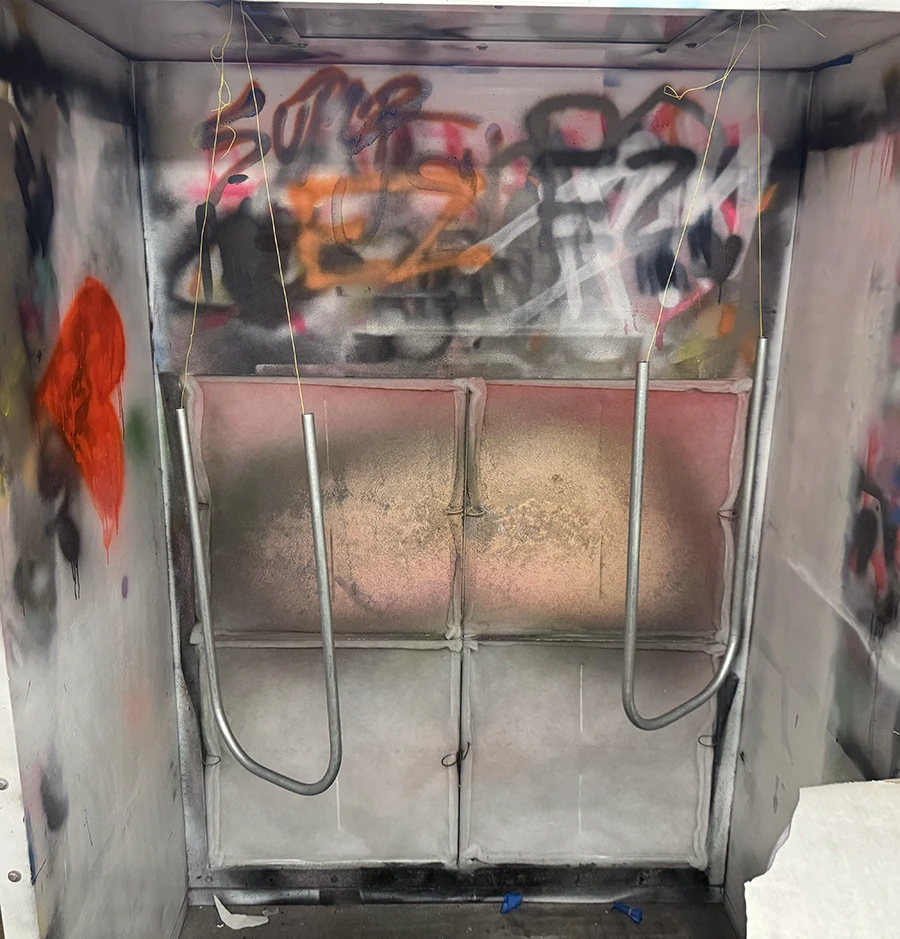
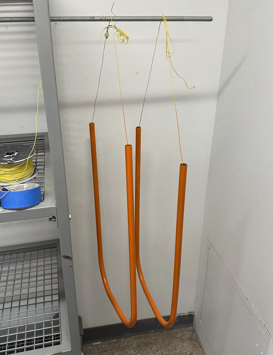
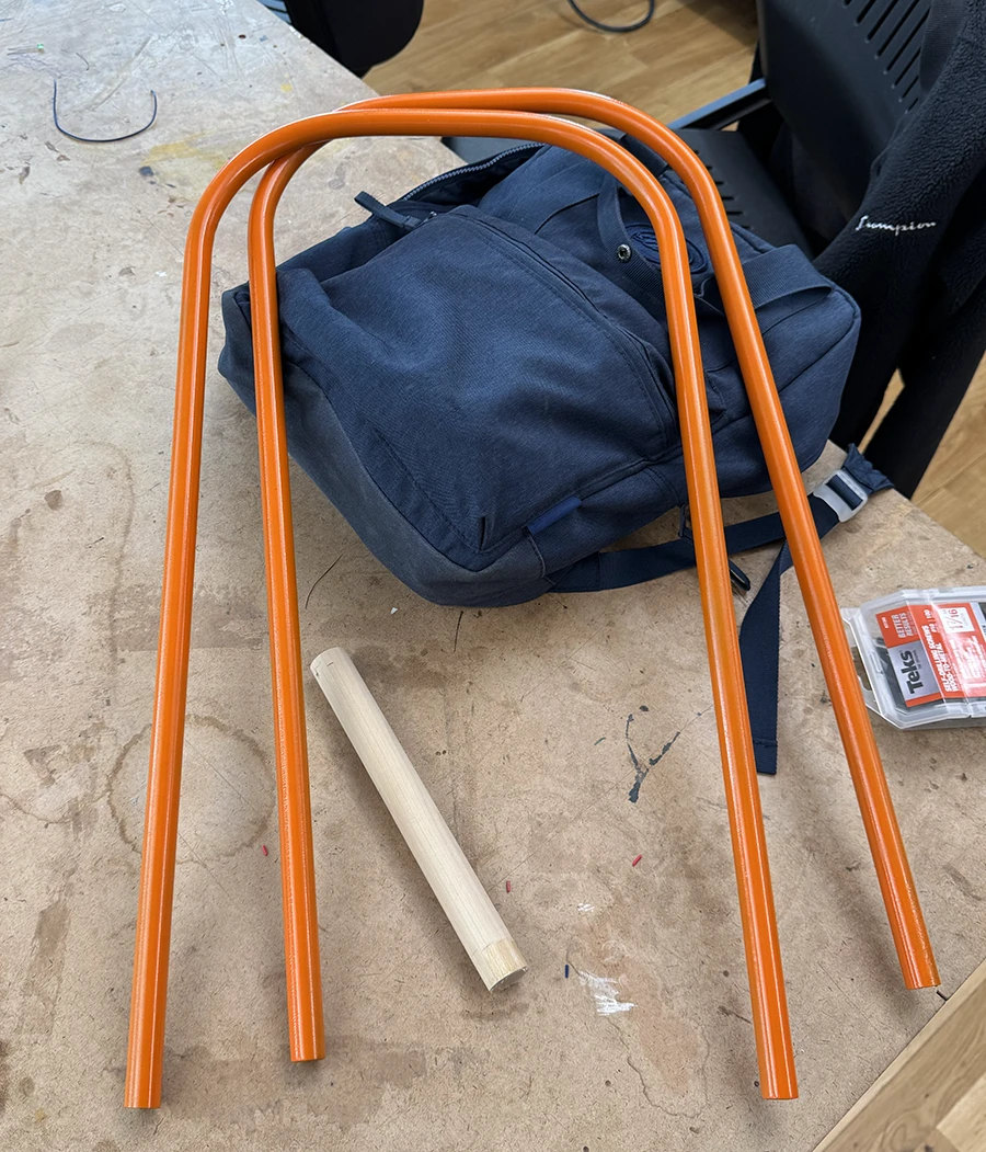
These were the tubes to be used for the legs. They are usually used in high quantities for electrical work, so buying just a few was not too expensive.A picture of me bending the tubes. Here you can see me doing it wrong, because I thought placing my foot on the tool was not necessary. However, it is imperative to get a correct bend. Otherwise the tube can move and mess up the bend.This was the result of those wrong bends. Also, after show it to Phil, he also believed I was too ambitious trying to get a fully rounded 90 degree bend, which might not be possible with this tool.I rewatched the maker pipe bending tutorial very carefully and placed the correct markers on the tube. Then I bent them and got this result.I used a metal hack saw to cut the extra tube on one side to level out the legs.I then roughly wet-sanded the legs with 320 grit, in preparation for painting.I hung the legs from the booth in order to paint them completely without having to do one side and then the other side.I then hung them on the side of the drying shelves.Two days later I picked them up and the paint had a very nice texture. Although, because I didn't have enough time to use the primer or the clear coat, the finish is somewhat fragile.
In parallel, I was also working on the tabletop, made out of a solid wood plank.
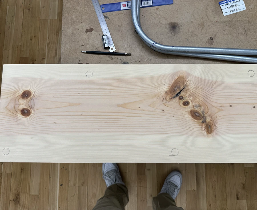
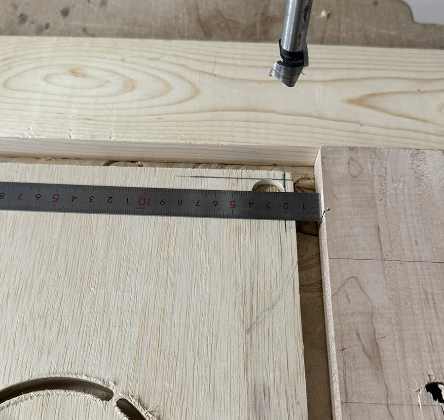
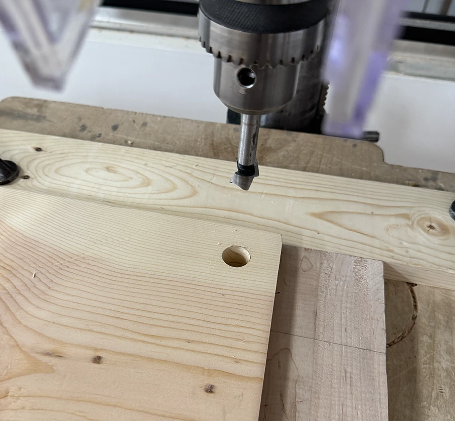
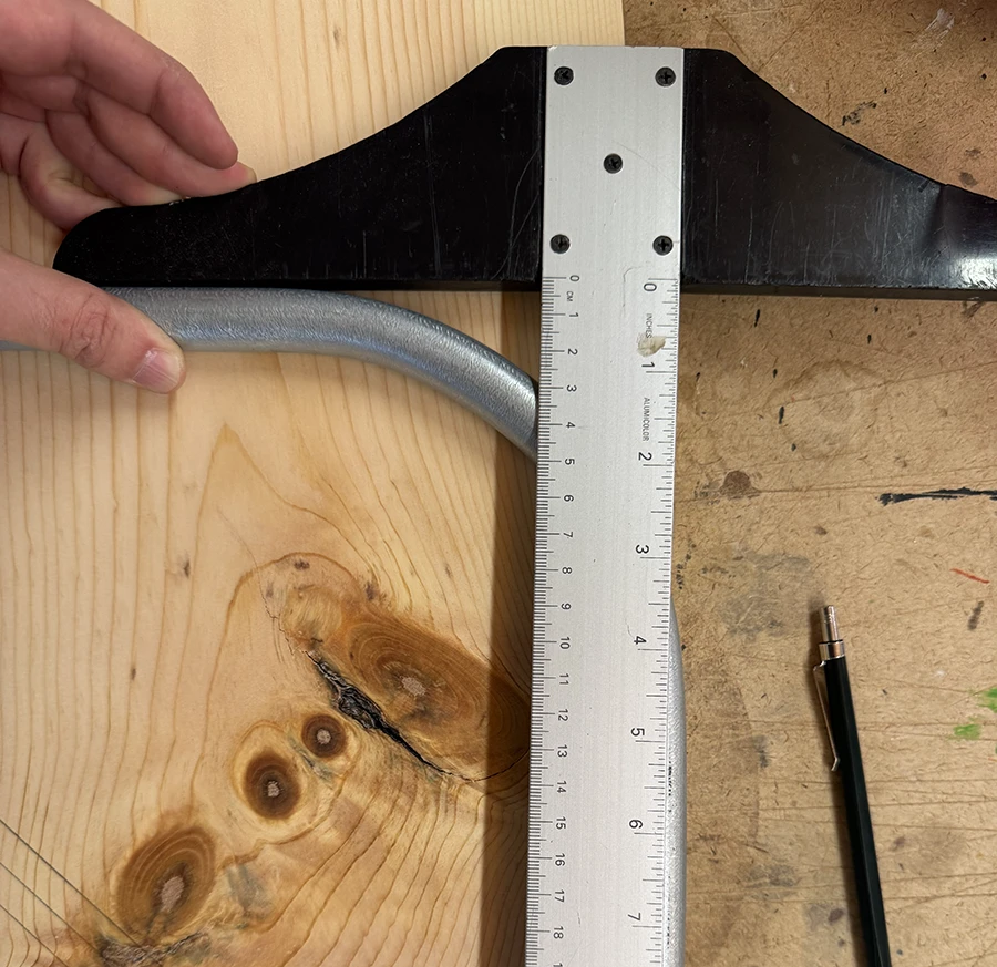
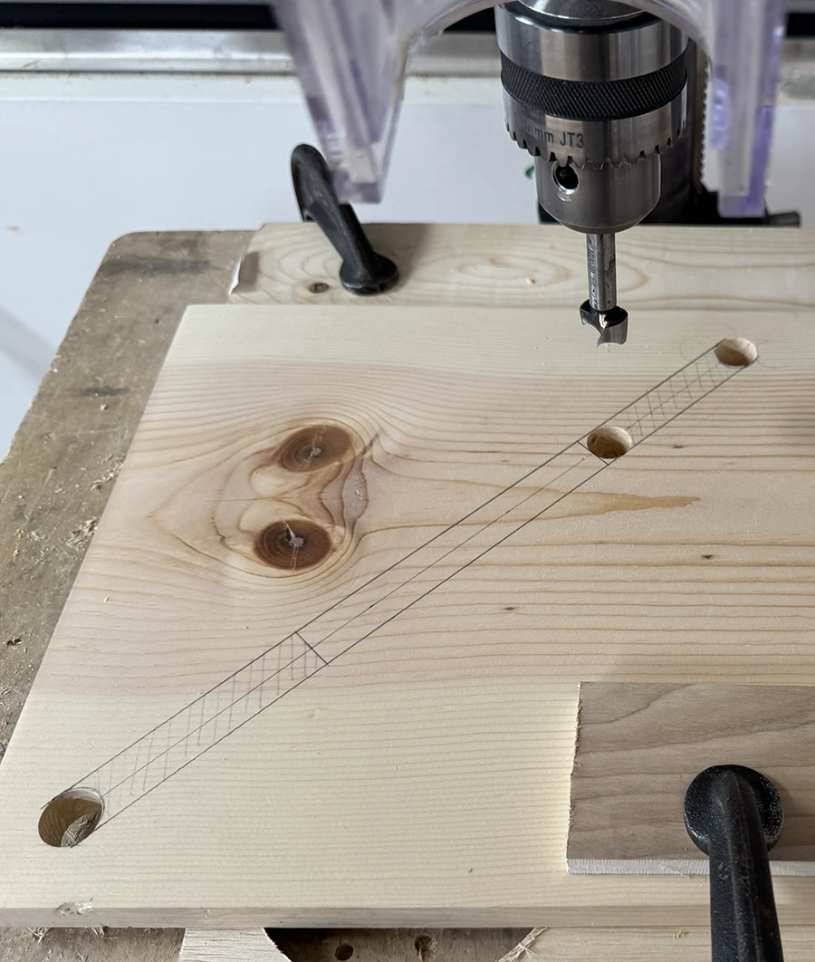
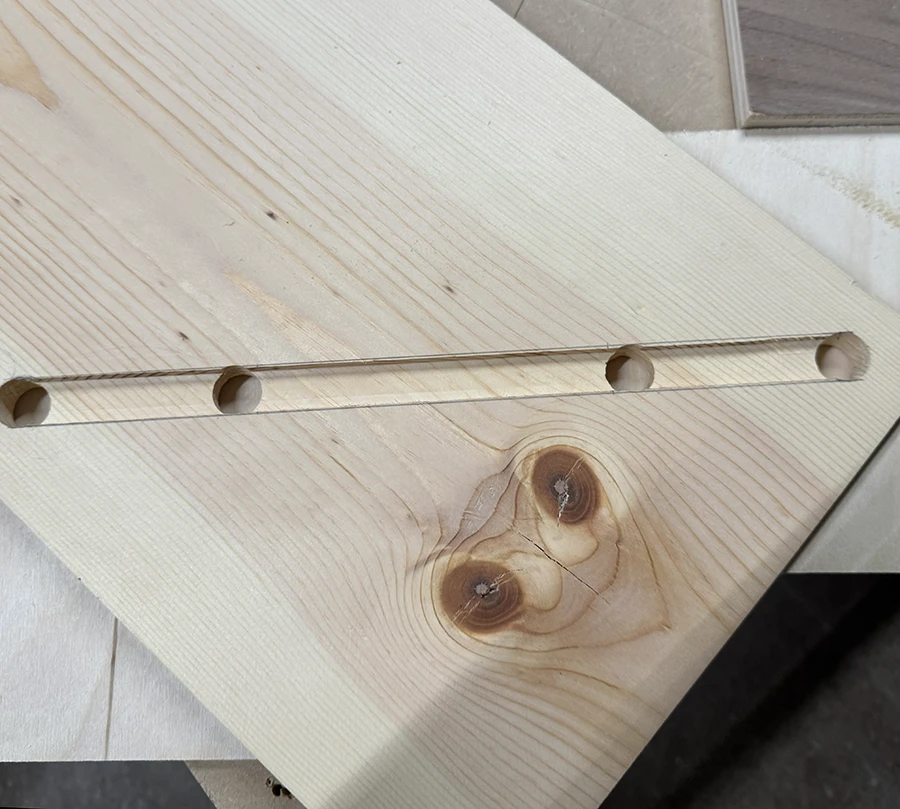
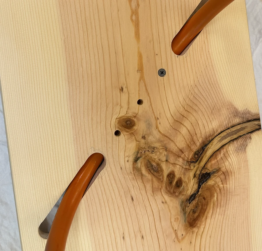
I bought a wooden plank and decided to make the table the exact size of the plank. I started by roughly sanding the plank and then making the markings for the 4 holes.I made a jig to keep the holes 20mm away from the edges of the wood plank.The holes made by the jig fit exactly in the markings I made. Very satisfying.At this stage, I tested the fit of the legs in the table.I measured the length of the bend on the table leg, to figure out the size of the slots required so that the legs could go through and sit on top of the tabletop.I measured and marked the different parts of the slots to be machined, and then cut holes on the ends of each slot.
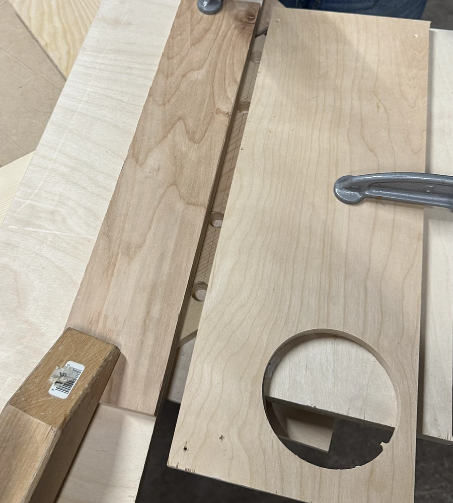
At this point I had to use the router in order to make the channel and the slots through which the legs would pass. Although I had gone through the demo, I was a bit unsure of using the router, so I asked my friend Niko for some guidance.
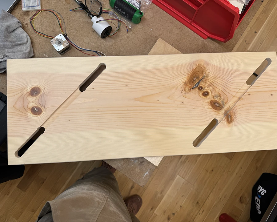
We clamped long pieces of wood on both sides to create a channel that would guide the router bit.This is the resulting channel created using that setup. I then clamped the piece of wood on its own hanging over the side of the table, and used the router directly over it for the slots that had to go through.Once this was all done, I used the roundover bit all around the tabletop. I also sanded the wood up to 600 grit and then added a few light coats of tung oil, buffing it out with a rag to make it shine a bit more.
Finally, I figured out how to fasten the legs to the tabletop.
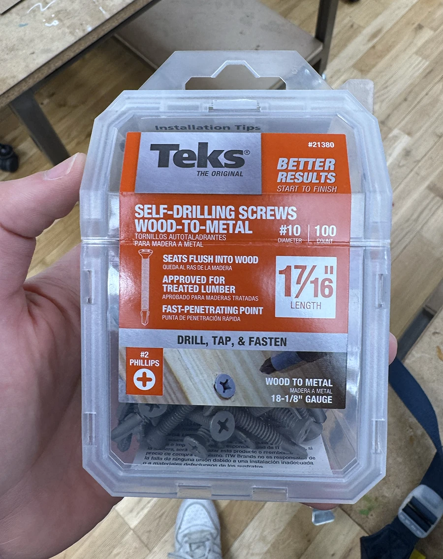
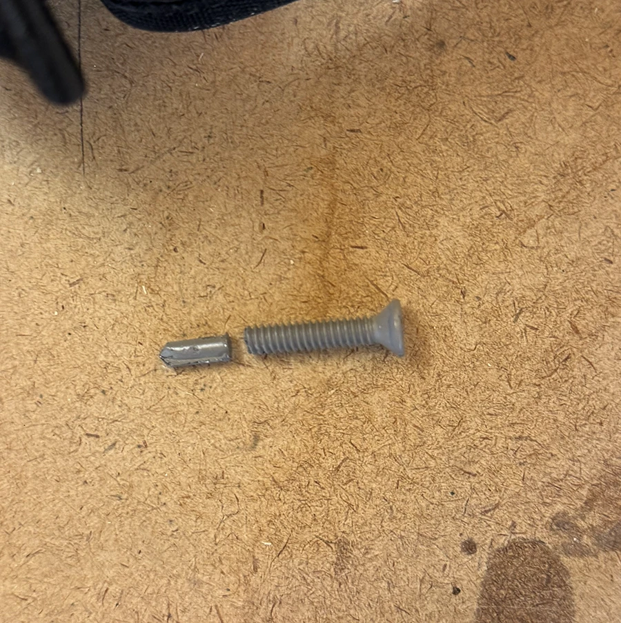
I bought these self drilling wood-to-metal screws in the smallest length they offered. However, according to my calculations, they were a bit longer than what I needed. So I tried to make some wooden spacers for them, but they didn't work very well and the screws didn't grip the metal.In the end, I decided to use the screw to make the hole in the metal legs, and then take it out, cut the drilling part off, and then screw it into the metal legs. This way, the screw was no longer too long.This is what that looked like. It was very difficult to get the legs to be perfectly aligned.
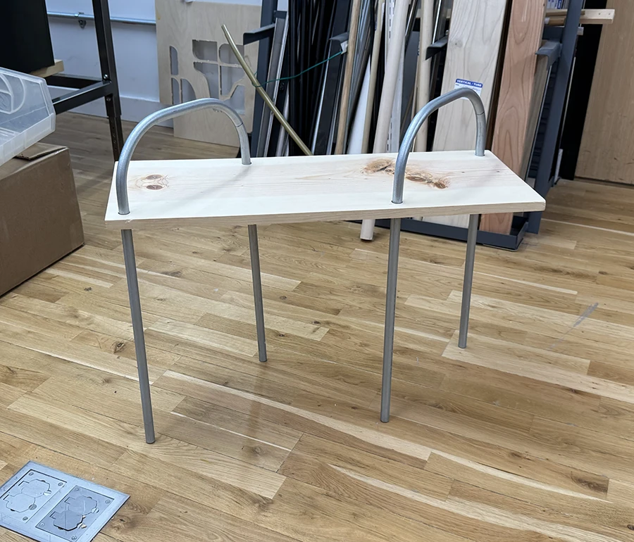
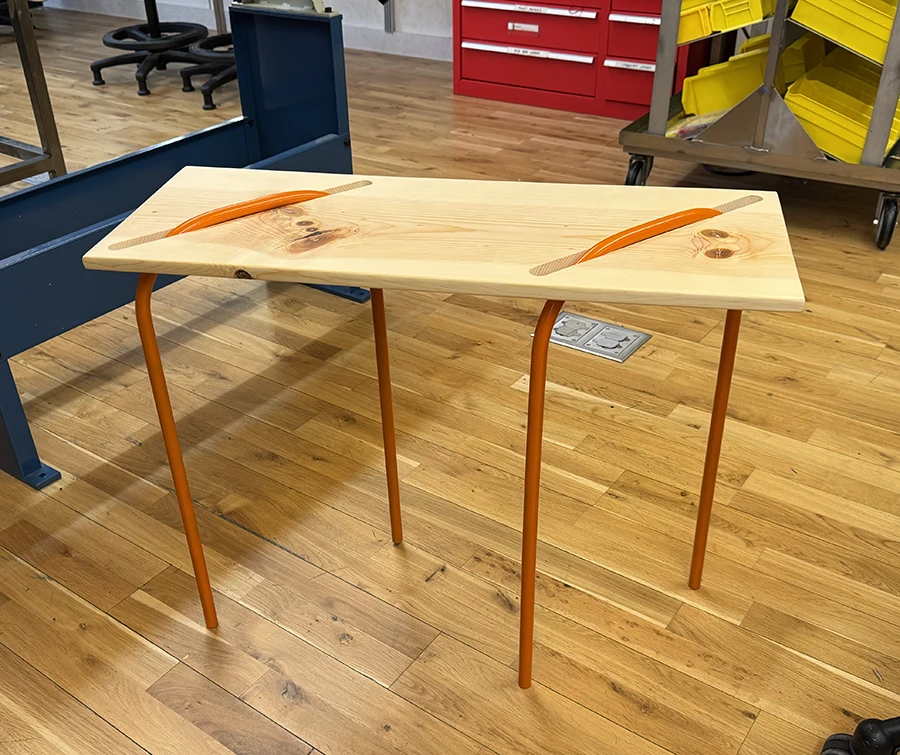
With that I was done:
The final piece. Because of the difficulty aligning the legs, one of them was a bit longer which made the table wobble a little bit.
Week 04
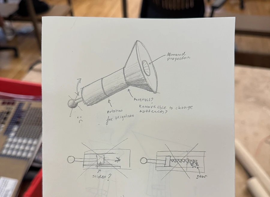
This fourth week was dedicated to enclosures, using the techniques we have learnt plus possibly the router. I decided I wanted to make a flashlight, which was ambicious in hindsight, given the limited time.
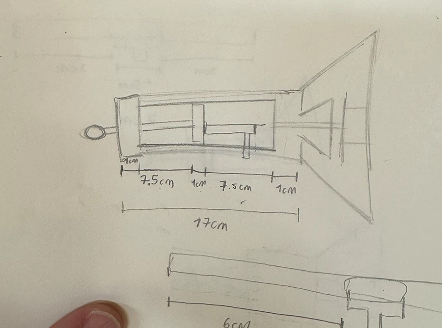
The design I made for it was a simple dowel as a handle and a larger cone-shaped piece for the light to project out of. From the base of the handle pops out a small dowel with a sphere, which can be pulled/pushed to dim the flashlight.I made some measurements (which would later change) based on the way I would structure the inside. The idea was to have the interior lined with plastic tubing. The piston would pass through a plug that fits tightly into the tube. It then keeps going and grabs hold of the bottom of an upside down slider. The wiper on the slider is held in place as it is mounted on the tubing lining.
After planning out the logistics with the help of Phil, I went on with getting the parts to be enclosed.
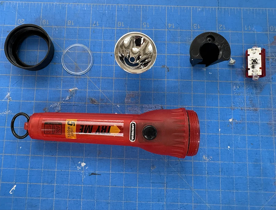
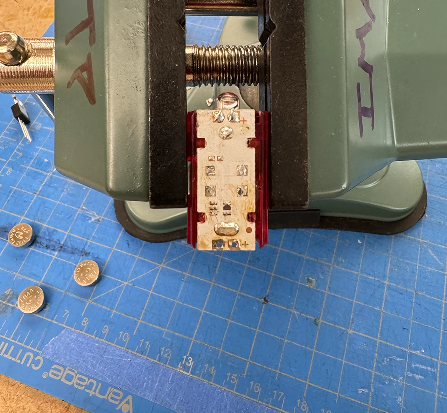
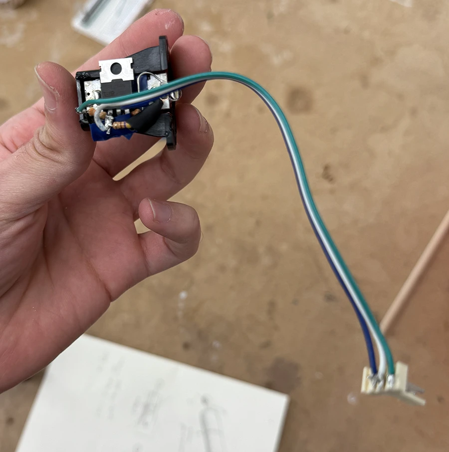
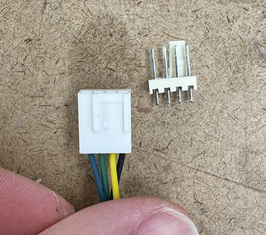
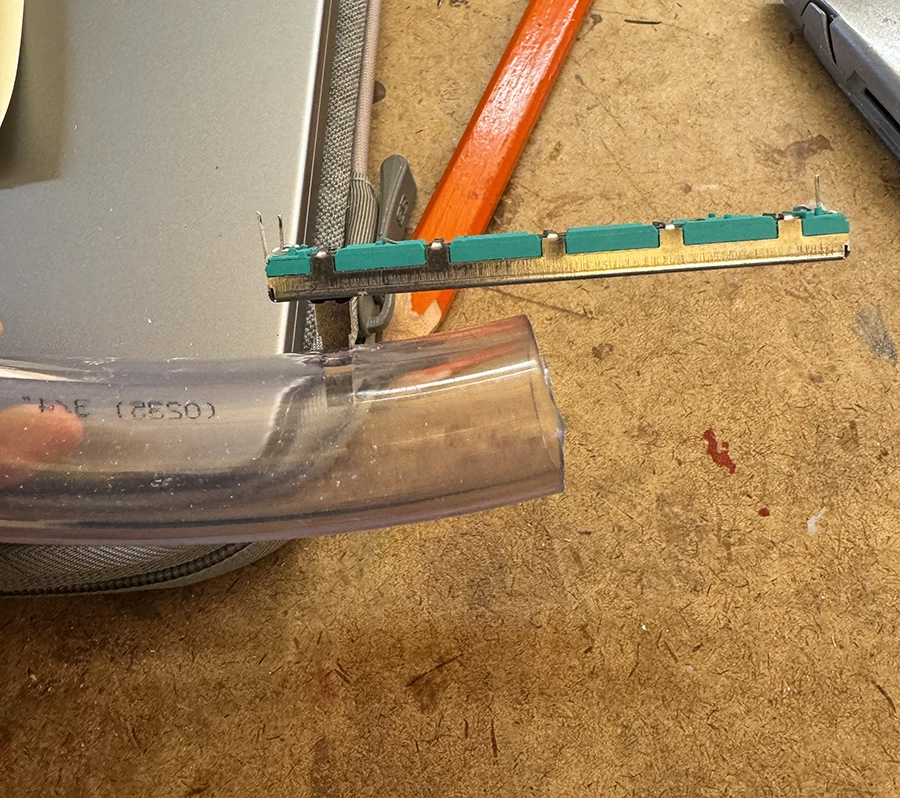
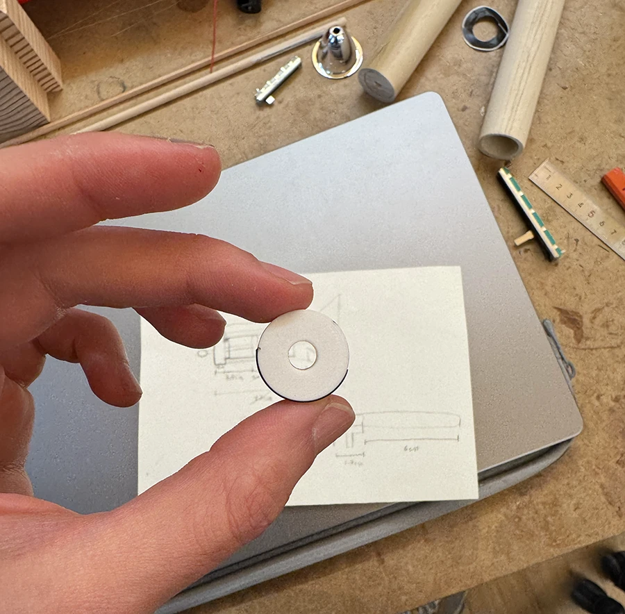
I bought a cheap flashlight and tore it apart into its constituents.I analyzed the circuit to understand how it worked, since the flashlight had 5 different modes. It basically consisted of the LED and an IC that controlled those modes. As I couldn't find a datasheet for the IC, I assumed it was a custom solution for this product. So I then decided to desolder the ic and the button, and leave only the LED and battery terminals.I built a simple circuit using a mosfet to control the dimming of the flashlight. The beauty of it is that the mosftet takes negligible current to control, so when the resistance of the potentiometer is very high, basically no current is being used, saving battery power.I then soldered the circuit trying to keep the smallest footprint possible.I decided to use these terminals for the connection to the potentiometer, since I wanted it to be easy to disconnect if the need arises, so that this piece can fully come out of the flashlight.Small test trying out the idea of holding the potentiometer from the taper by pushing it into a small cut on the side of the tube.3D printed plug for the tube, which would hold the piston steady.
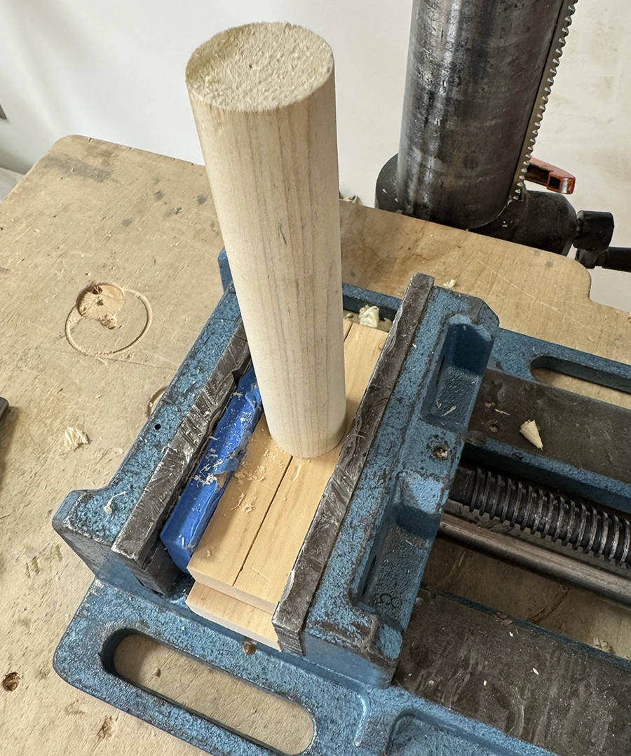
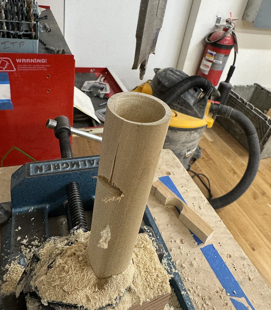
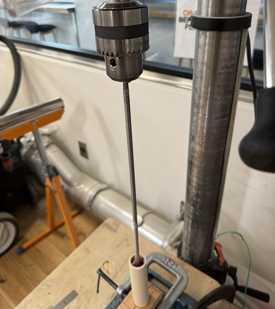
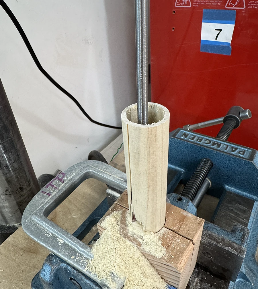
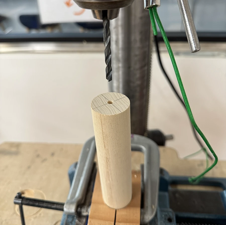
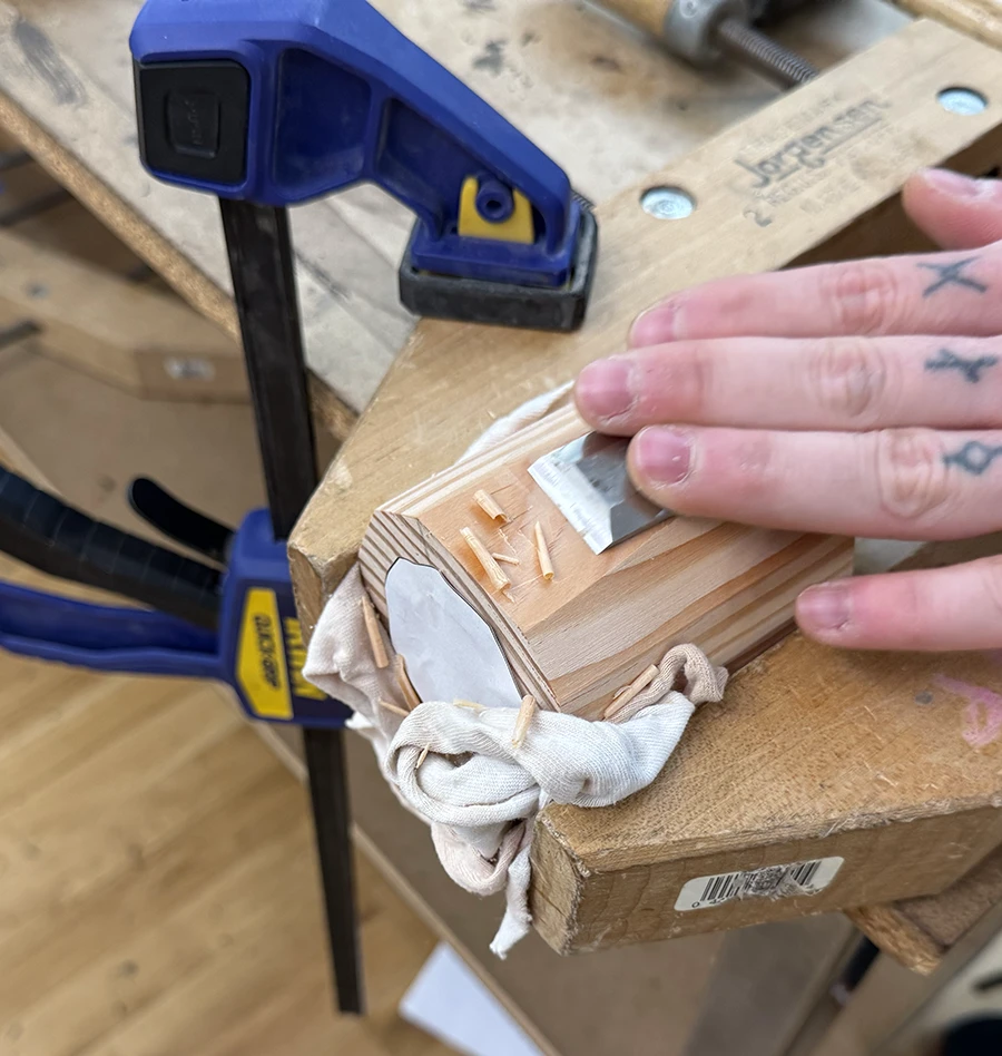
I then moved onto one of the big challenges of this build: hollowing out the handle.
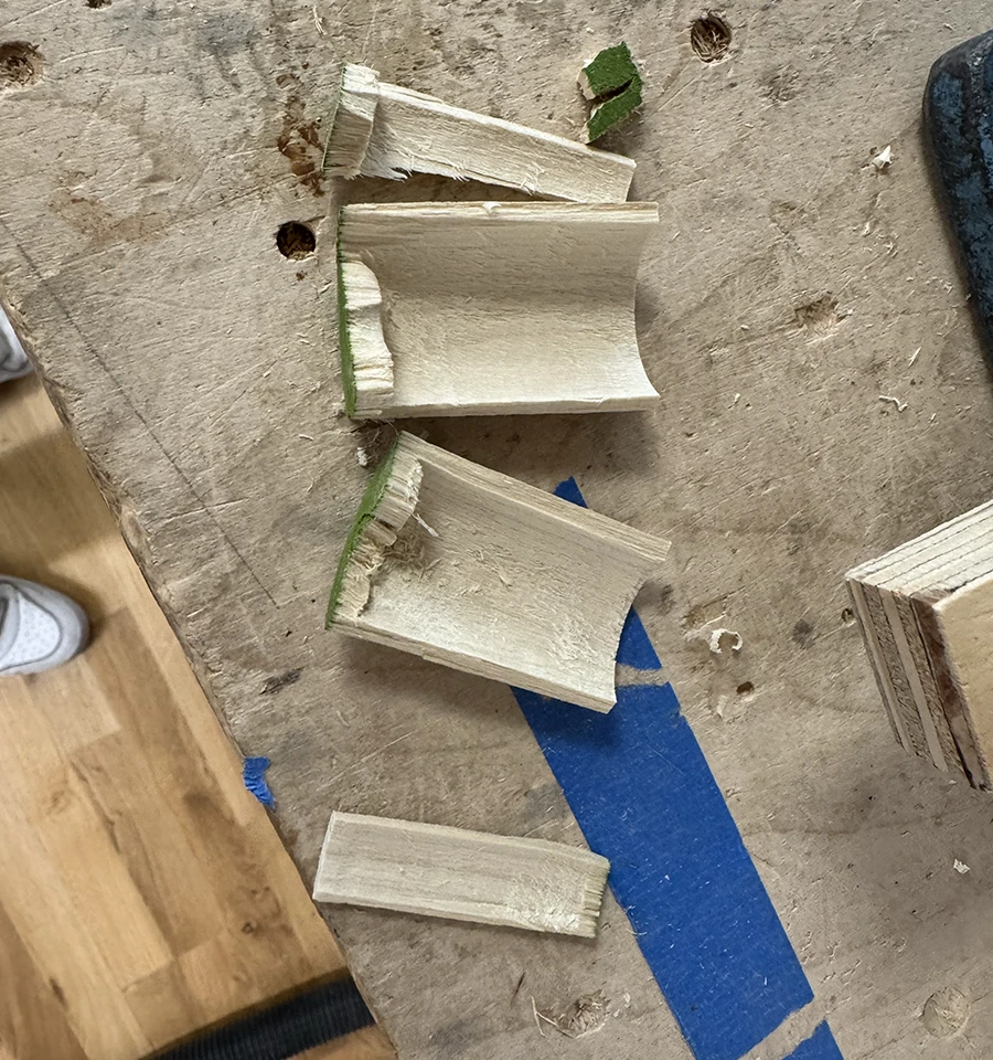
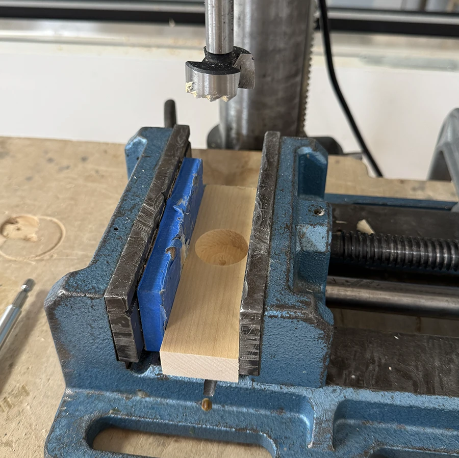
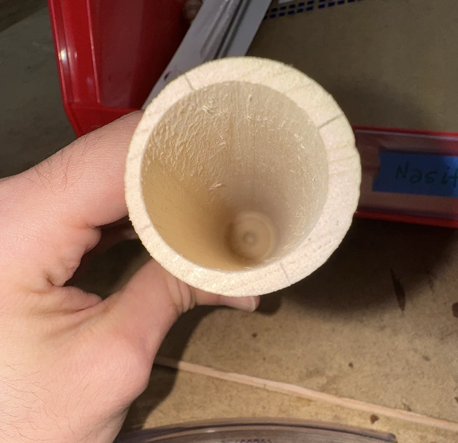
This is the first test I did cutting into the cyling with a spade bit (since it was the longest one). After this one, I managed to cut into one of this small test cylindes.I made a jig that would accomodate the dowel.Holding the dowel on the jig with the vise.Another failed test, still using the spade bit with a bit extender. At this point I realized that the bit extender was really imprecise and very tricky to get it to go deep in a perfectly straight line.I made a new larger jig that could give more stability.Kai instructed me to use a glove to add even more friction and keep the wood steady in the jig.I also decided to buy a long spade bit, as I believed it would be more stable than the bit extender.Although deeper, this new test also broke the wall of the dowel, which meant it was still going in at a slight angle that would eventually eat up on the walls.I made a pilot hole on the base and used it to place the clamped dowel as center as I could with the spade bit, trying to get as close as possible to a perfectly straight cut.Finally this worked. It still went in at an angle because, when looking in, one of the walls at the bottom lets in more light than the others.
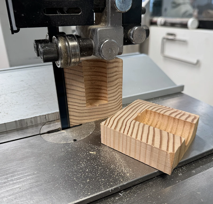
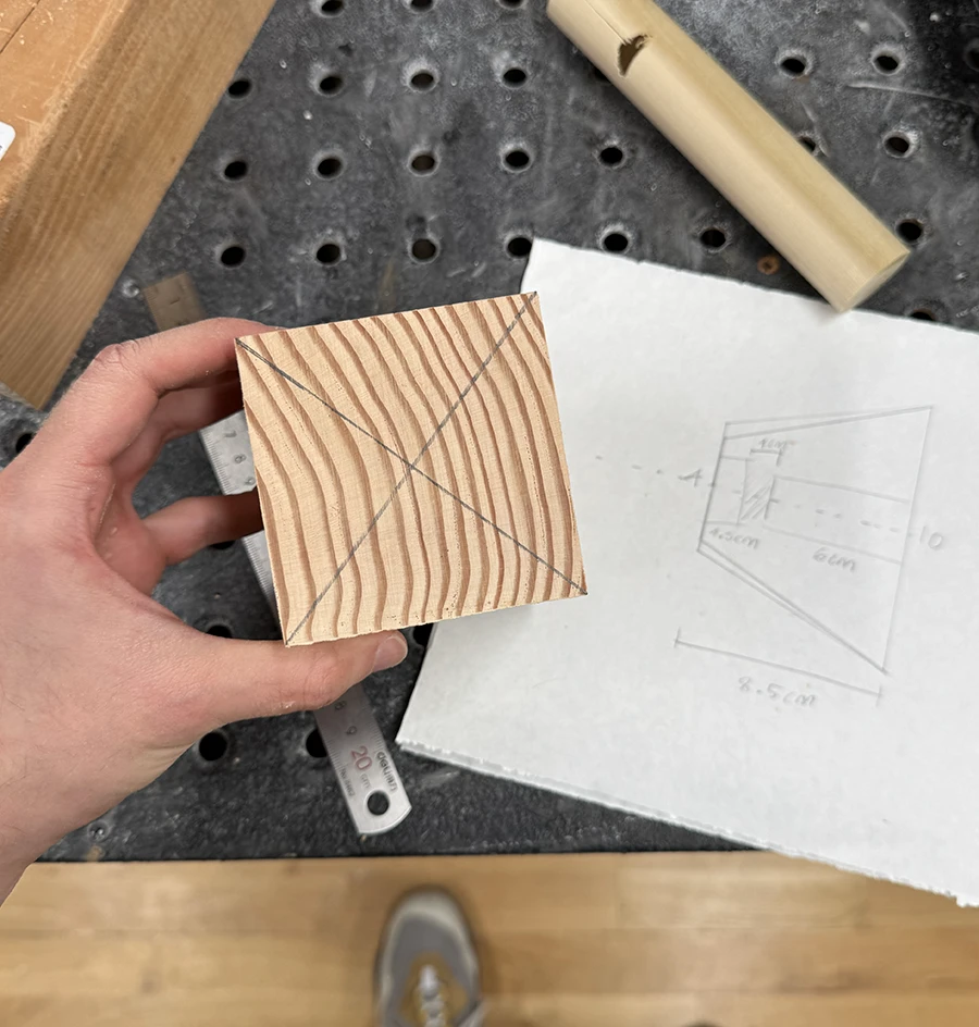
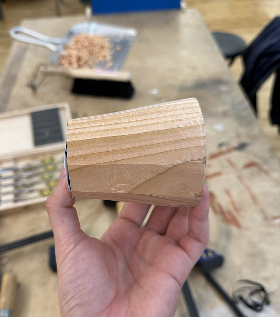
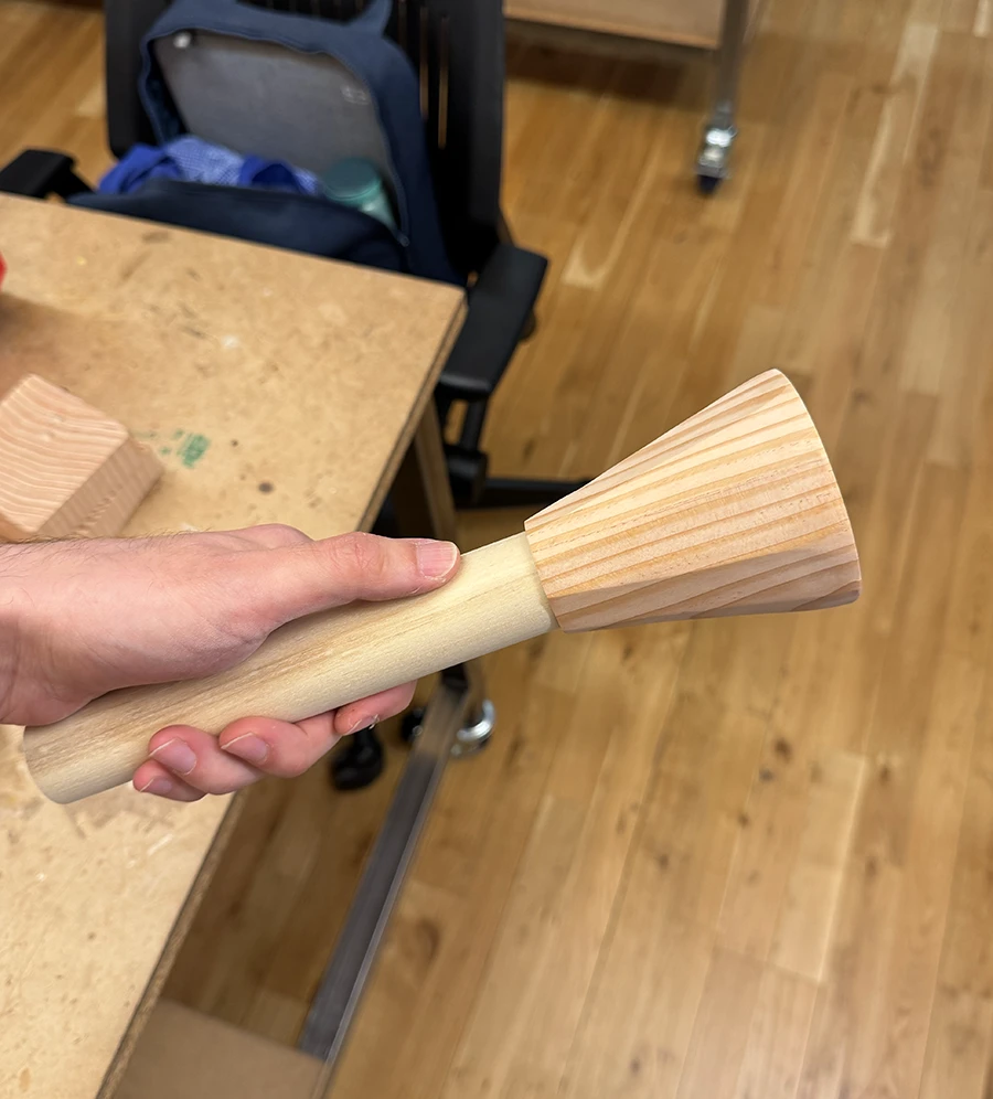
Once the first challenge was overcome, after spending two days on it, I started working on the cone for the projector.
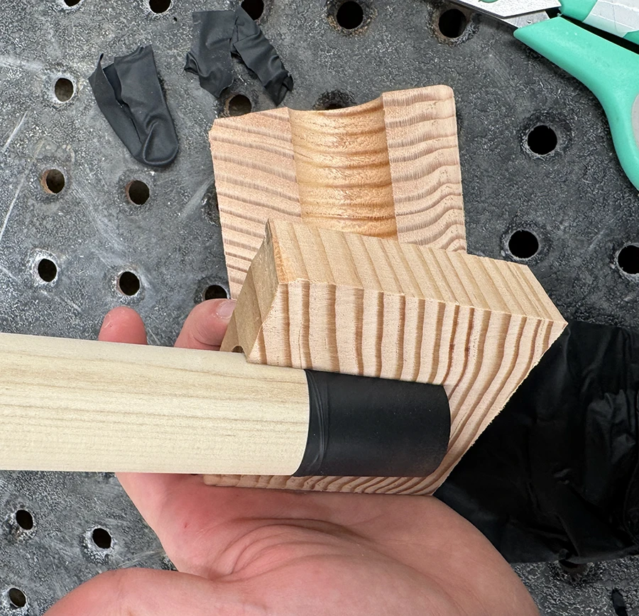
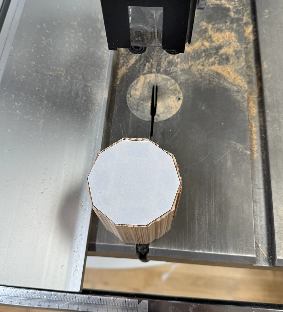
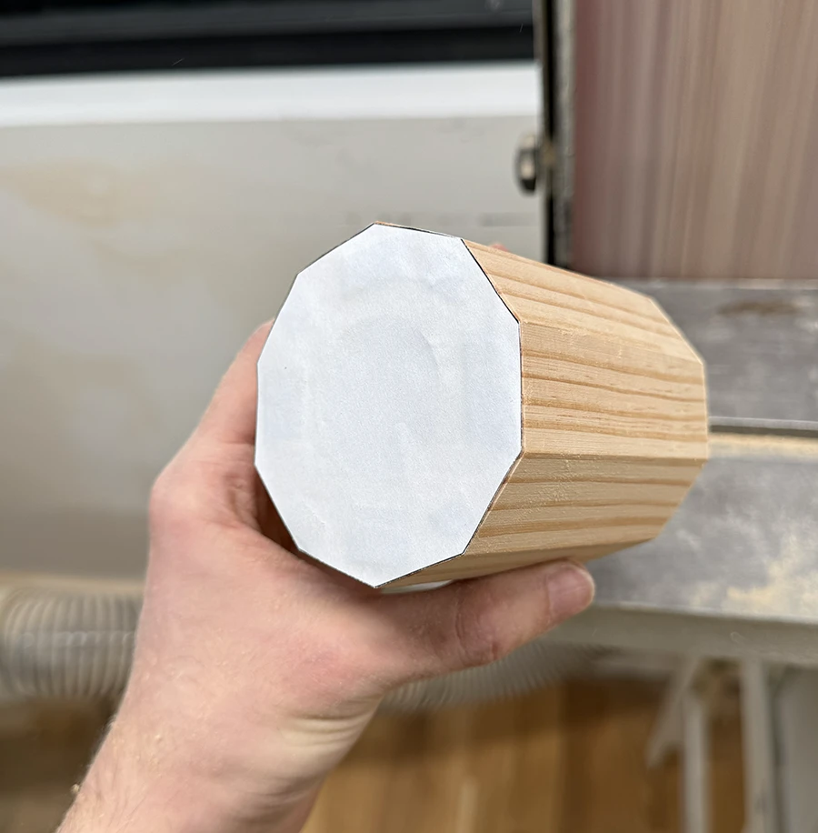
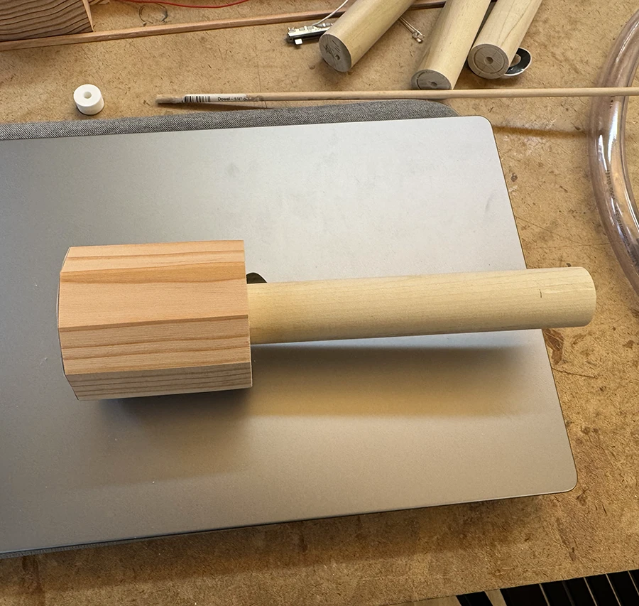
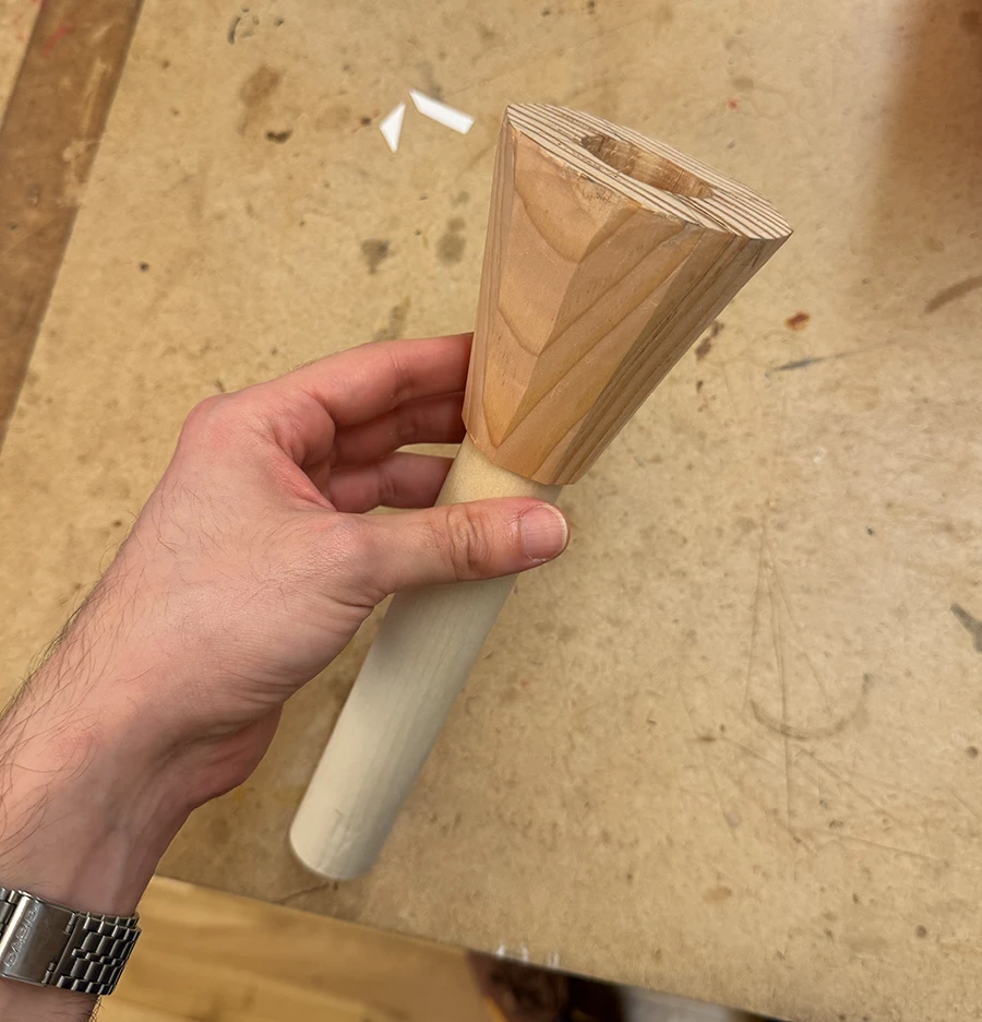
Started by cutting and squaring out a block of wood as best I could, in the dimensions of the projector.I printed a decagon the size I wanted and taped it to the piece, which I used as a guide cutting it out on the band saw.I then sanded it down, taking care to maintain the faces that I wanted for the final piece.I also made all the holes from my diagrams and tested out the fit with the handle. Initially I wanted to do a dovetail joint but I scrapped that for the time being.Since I wanted this piece to taper down, my friend Niko lent me his wood carving tools and taught me how to achieve this. This way I could maintain the faces instead of rounding it out.I printed another decagon, smaller, to use as a guide on the side that was to be smaller. I then carved it down to that size, but I still wanted it closer to the handle size, so I printed a new decagon and kept going.The piece after carving it down to the desired size.
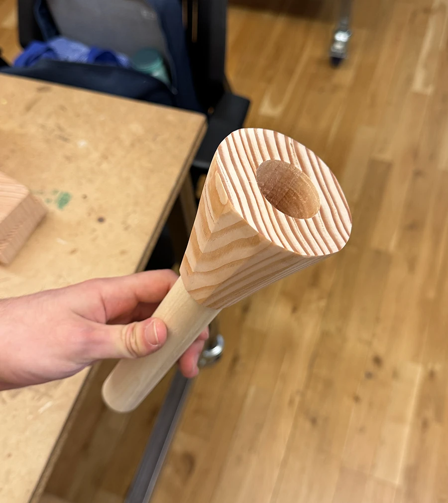
Once this part was done, I sanded it all down to 400 grit to give it a better finish.
The sanded down enclosure.The sanded down enclosure.
Unfortunately the week was over by this point, so I will have to continue past the deadline.
Week 03
For the third week we had to work with the laser cutter, making the same piece in two different scales, and using some sort of joinery.
I really struggled with this assignment since I very much dislike the way laser cut wood smells and looks, and sanding does not really help if you need the precision of the laser cuts, which is its main appeal. After wasting a lot of time thinking around this, I settled with making a more decorative than useful piece: fridge magnets.
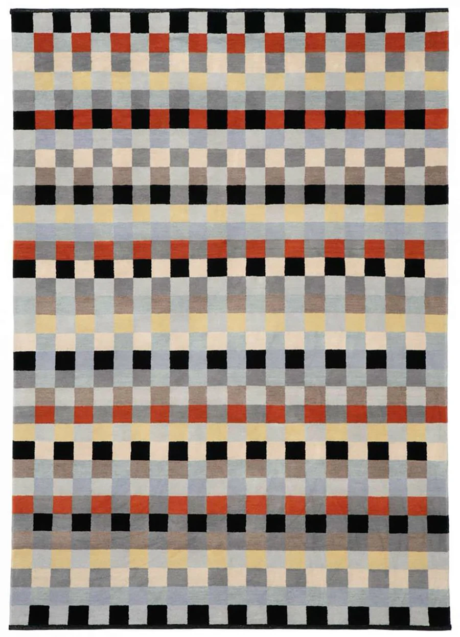
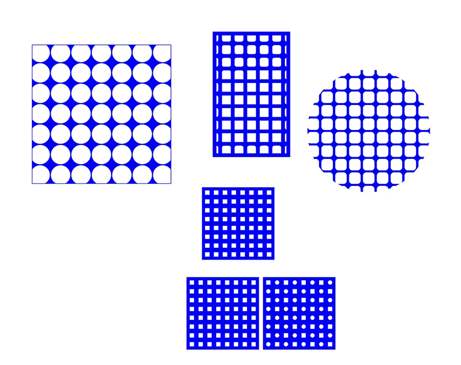
I was inspired by the work of Anni Albers, which is why I thought about making a geometrical design joining laser cut wood and acrylic.I tested some vector patterns in illustrator and ultimately opted for the square grid on the bottom, especially because I was unsure about how strong the wood was going to be with very thin lines.
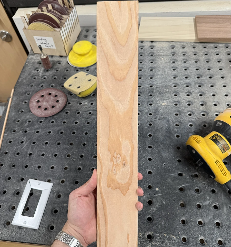
I began by preparing the wood and buying the right acrylic:
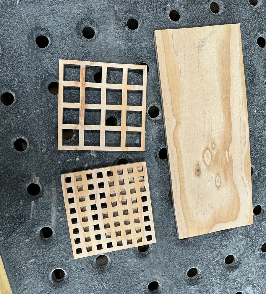
I sliced off a long plank of wood off of my large wood block, trying to approximate a 1/8in depth, same as the acrylic I had bought.I squared out the plank as best I could and sanded with 100 grit to get a clean uniform surface.
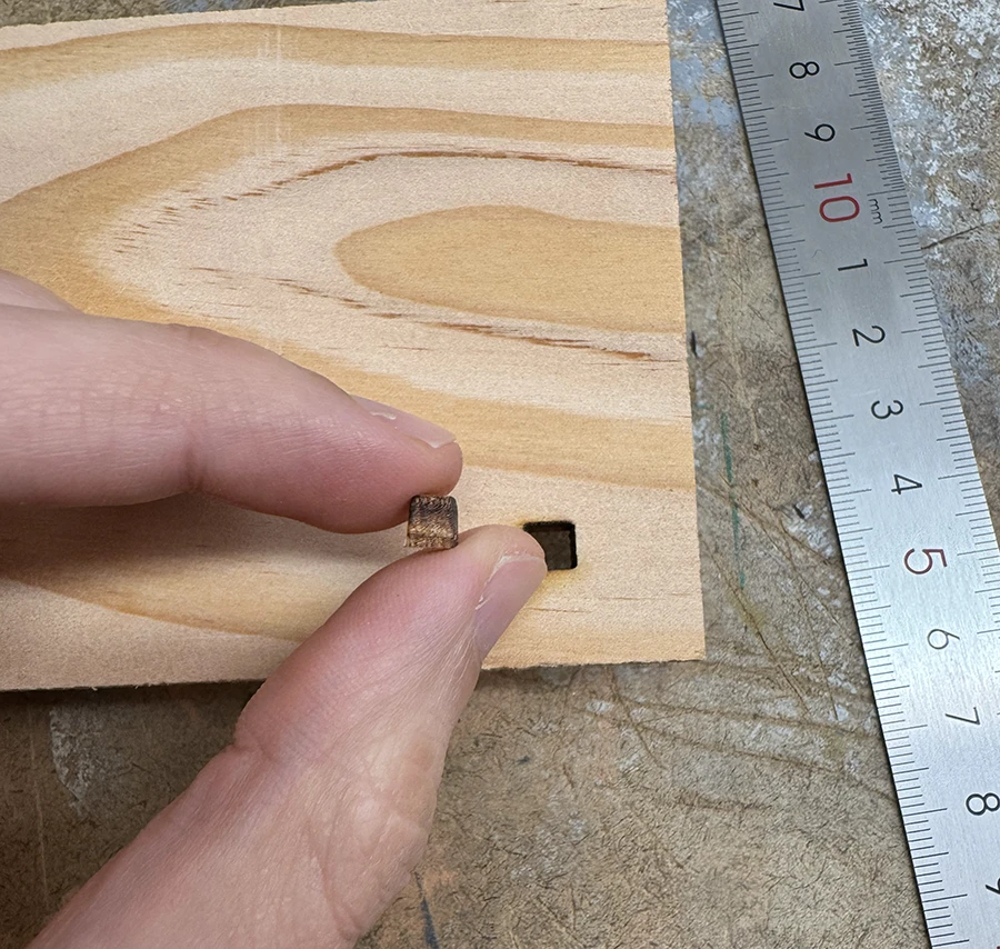
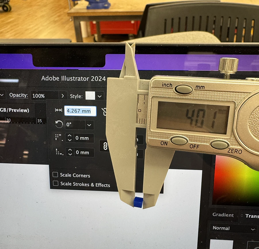
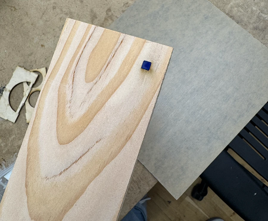
Once the materials were ready, I began testing the laser cutting and the curf.
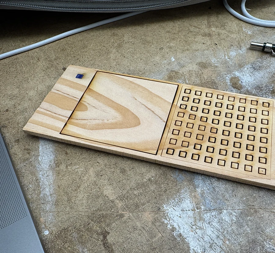
I began by making a square hole the same size of my design. I also measured the actual size of the hole and laser cut an equivalent piece in acrylic.The acrylic piece I cut was too small, which allowed me to calculate how much was lost on the cutting operation. I then re cut the square.The newly cut square fit, although a bit too snuggly. In hindsight I should've kept testing at this stage but I was satisfied with this result.
With my tests done (or so I thought) I began making the actual cuts
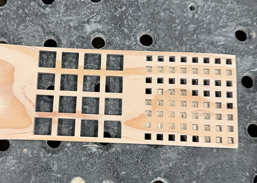
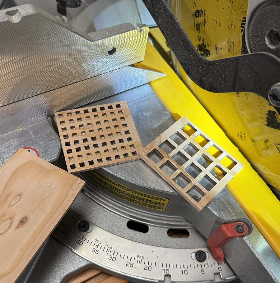
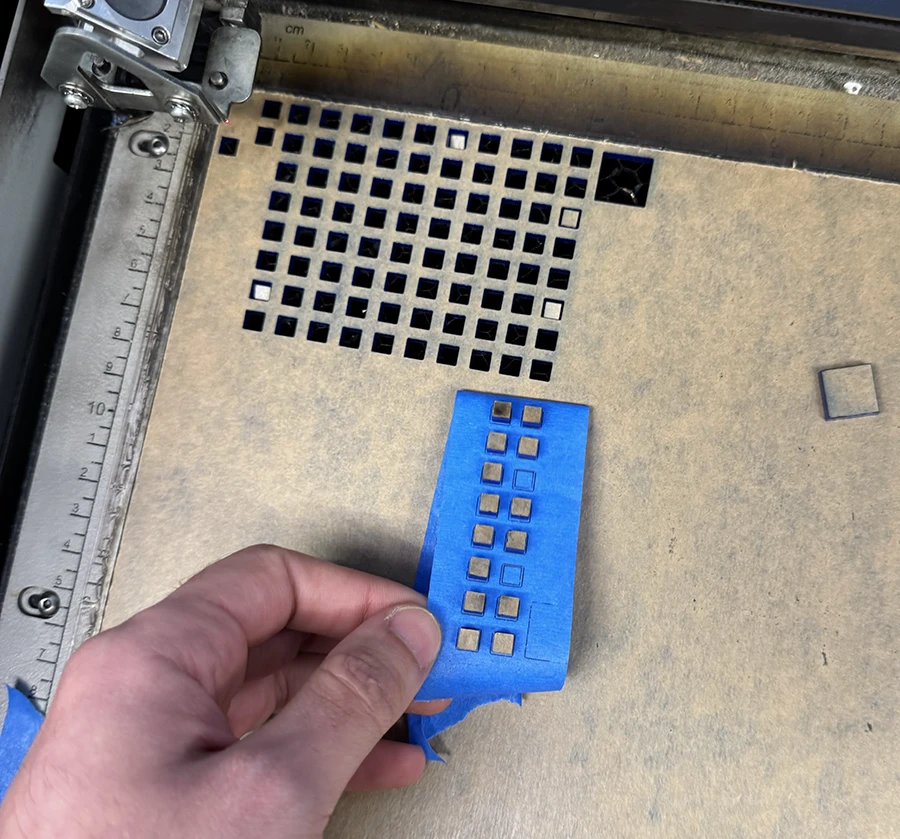
My first cut did not fully go through. Because my test cut before with the same settings in the same machine had gone through easily, I trusted this was the case again and removed the material.I redid the cuts in a new area, running the machine two times. It still did not cut through some squares. You can see that the incomplete cuts are always in the darker area of the wood, which makes me think this part is stronger. I sanded it down and scraped out the squares that were not cut through.I cut the pieces down to size using the miter saw, leaving a small gap to sand down.I then sanded down the sides and sanded the top surface to 400 grit.I cut out the squares and used some tape to recover the pieces so they would not fall down the grates.
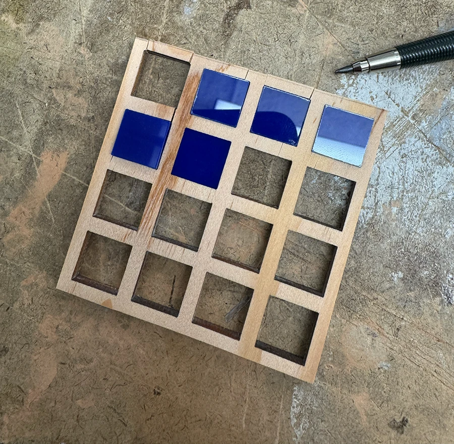
I also laser cut the larger squares for the larger version of the piece (which was like a zoom-in on the pattern). I used the same calculation of the curf for these pieces. With that ready, I started the assembly.
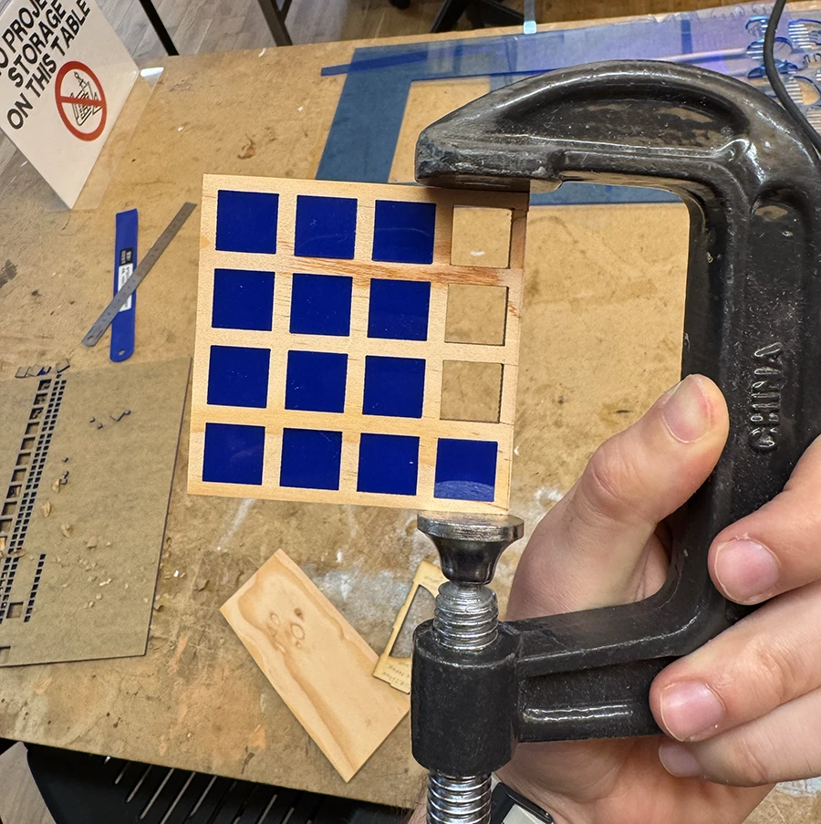
Upon adding the inserts, I realized they were exerting too much pressure on the wood and even caused some cracks. In hindsight, I shouldn't have sanded down the piece to size until it was fully assembled.I tested new sizes for both the small and large squares and then recut them. I also used some glue to fix the cracks.I assembled the small piece with the newly cut squares. Some fit easily, others required more force. Some small cracks are also visible on the perimeter but none as severe as with the larger piece.
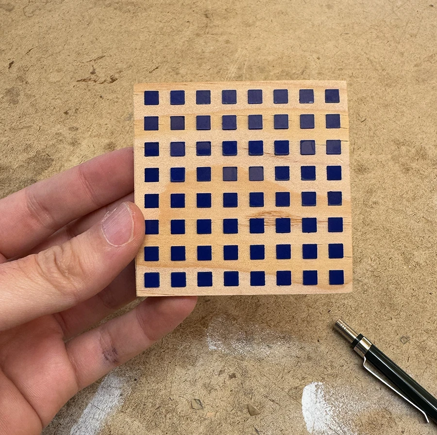
With this, my decorative pieces were done. I would then wait for the glue to set and stick a magnetic film to the back.
Week 02
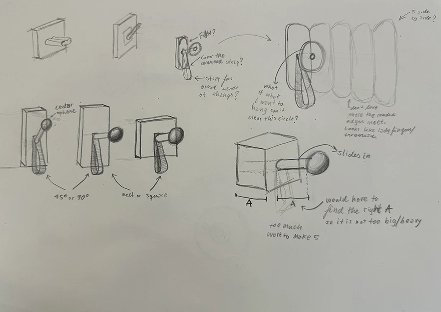
This week we were assigned with making 5 identical pieces. An exercise in repeatability and techniques like the use of jigs or stop-blocks. Since I've been thinking of buying some hangers for the apartment, I decided to make my own.
I began making some sketches. Since my theme are boolean operations, I want to make my pieces using mainly joinery, which can also be decorative.
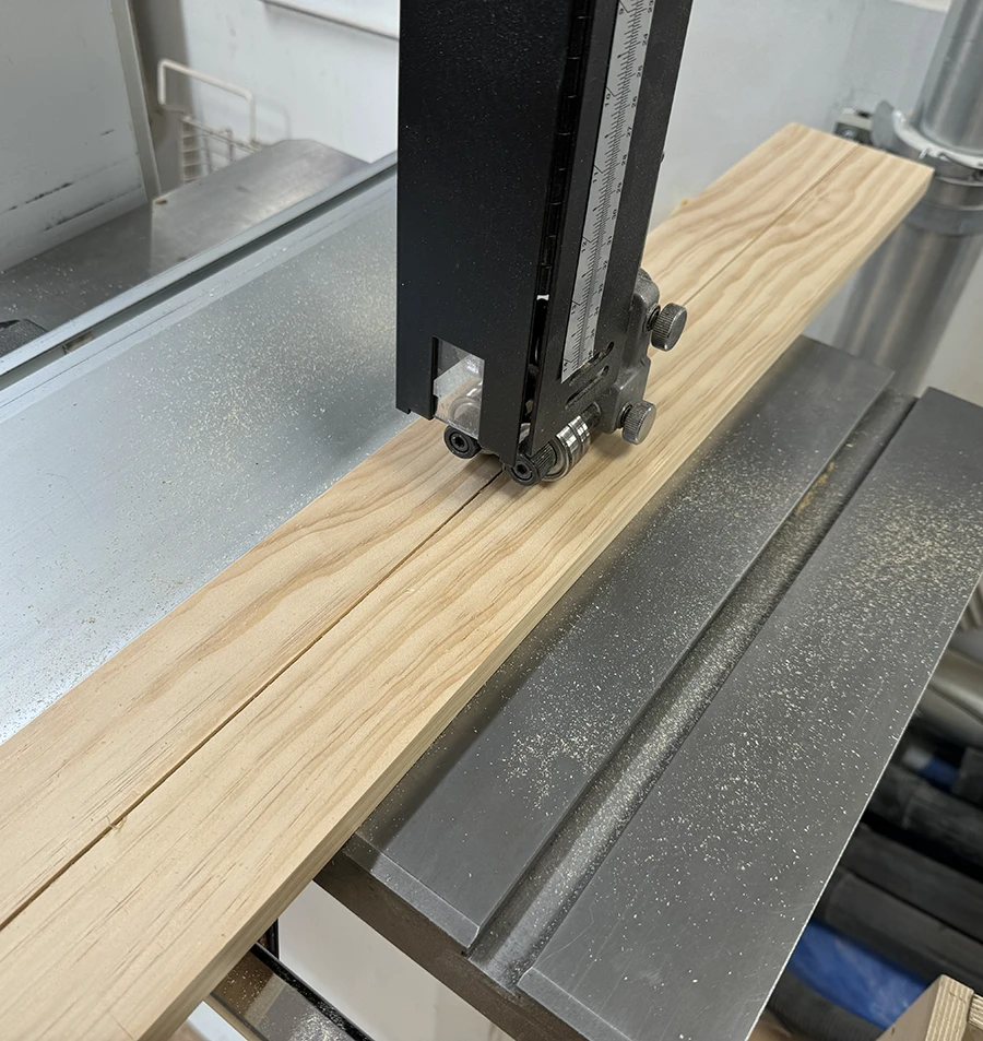
I began by working on the main block of the hangers. First I sanded the block up to 400 grit on all side except the ends.
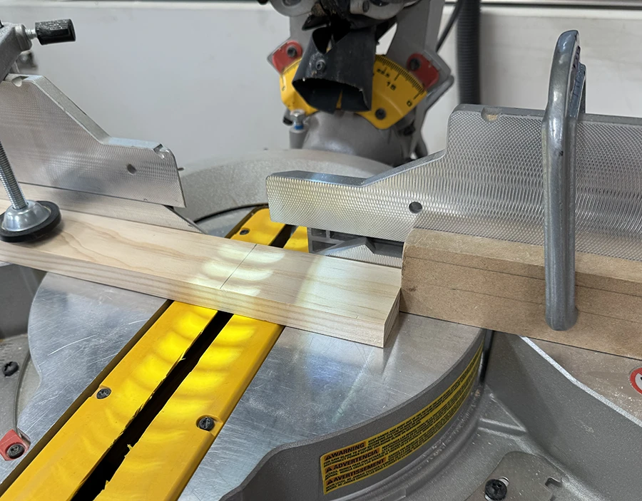
I used the bad saw to split the wood in half lengthwise.I then measured the length of each block and used the measurement to adjust a stop-block on the compund miter saw. With it I cut all my blocks to size.Once cut, I sanded the new edges up to 400 grit.
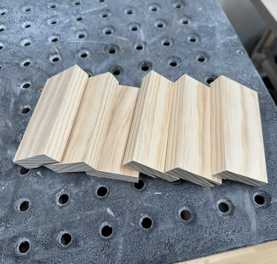
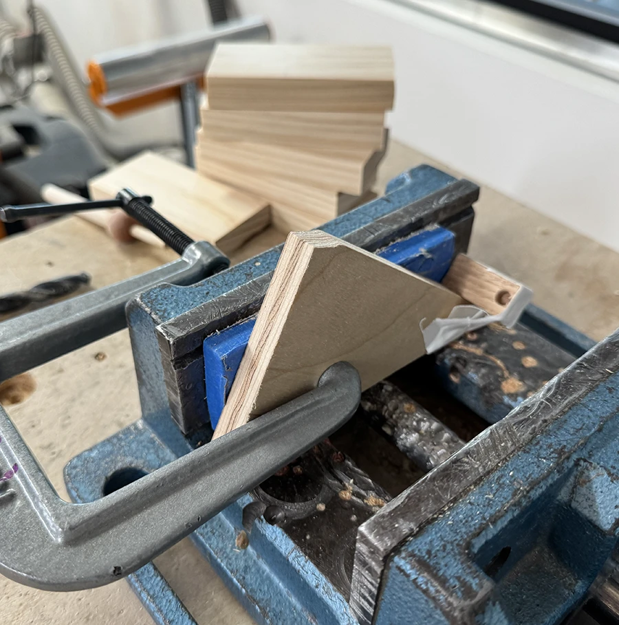
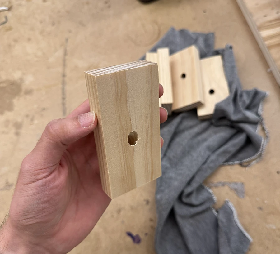
I then worked on the hole which would join the dowels to the main piece.
I set up a jig with a scrap piece of wood that had a diagonal cut on it. I used tape to hold a base block so the blocks to drill would have the same starting point when lying on the inclined plane.These were the results.
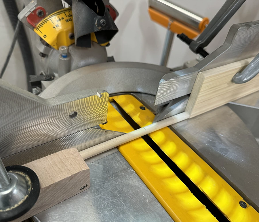
Afterwards, I worked on the dowel pieces of the hangers.
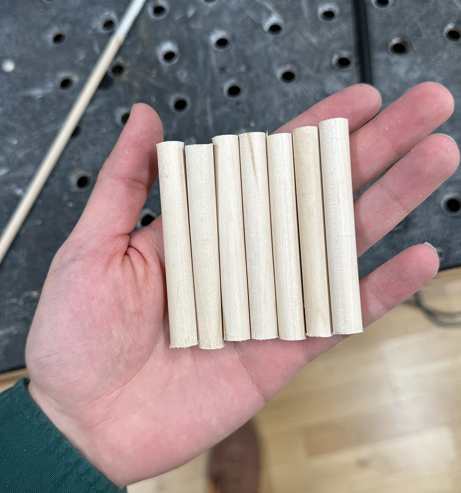
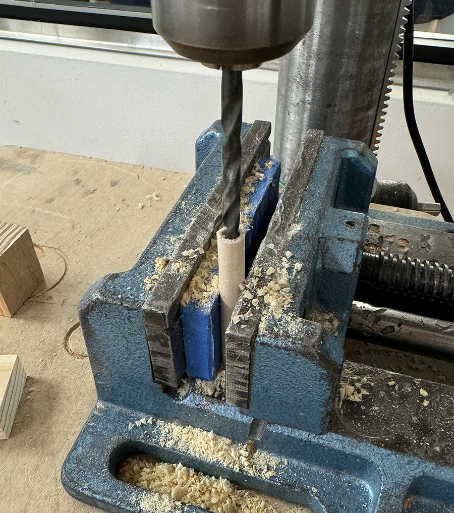
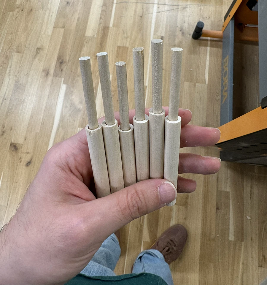
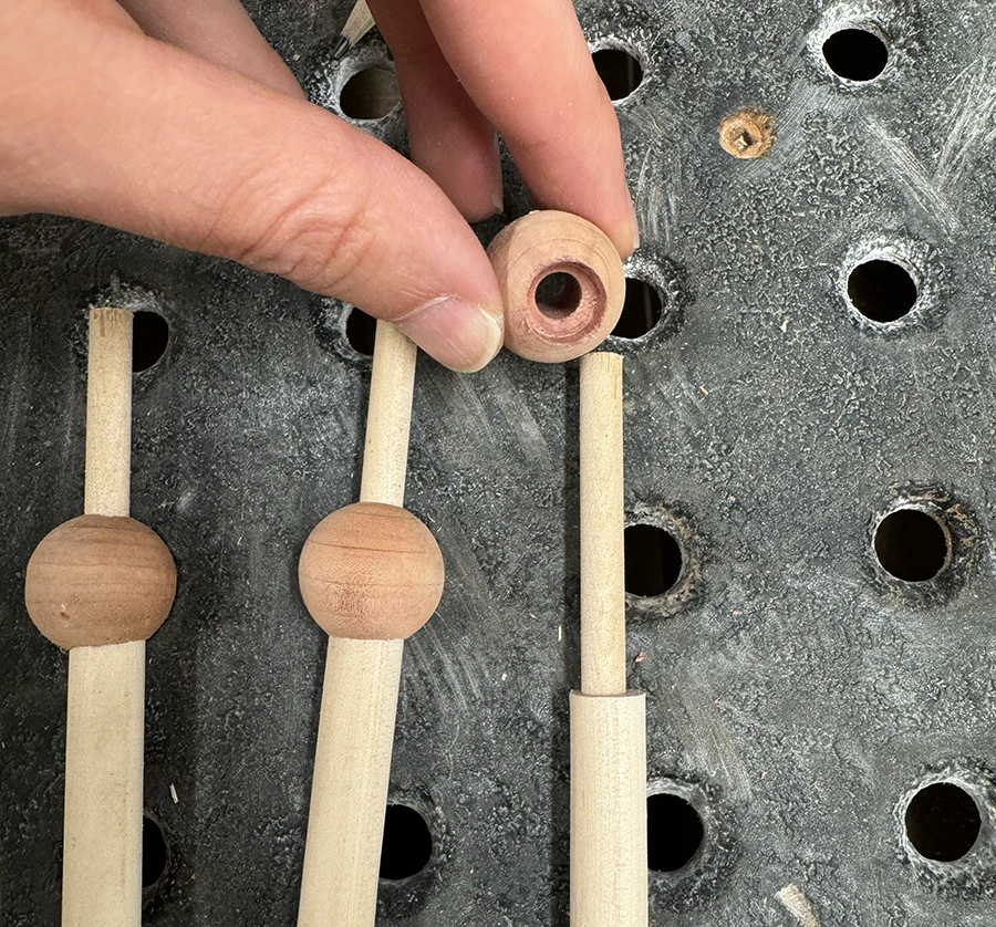
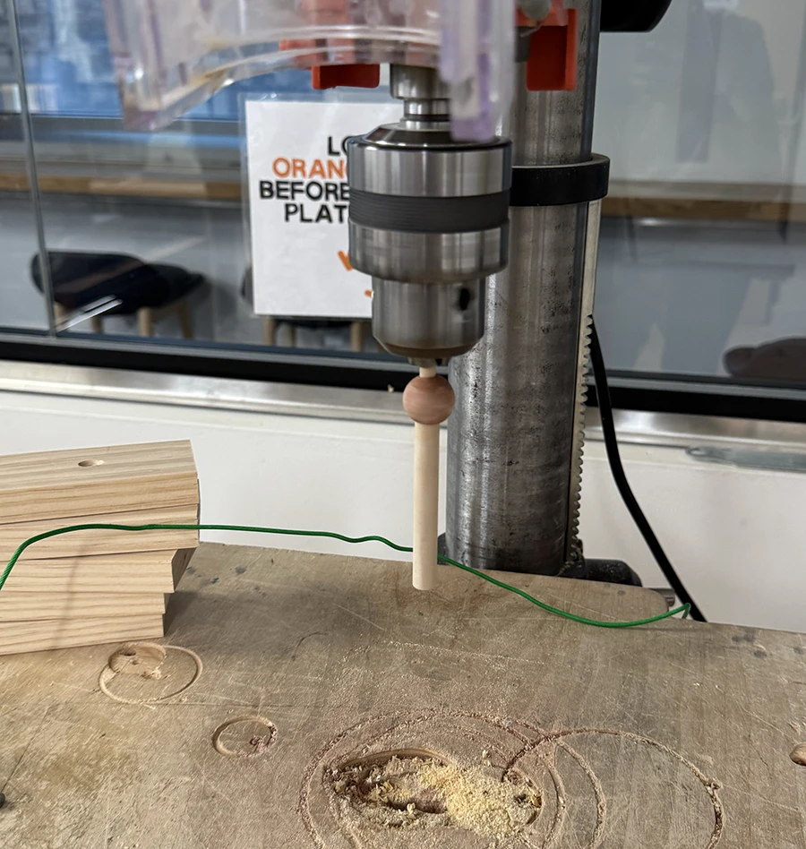
I measured the size of the hangers that I wanted (taking into account the parts to be lost in the joinery) and cut them in the miter saw with help of a stop-block.The resulting dowels.I used the bench drill to very carefully make holes into the dowel from the top, as to fit the smaller dowels inside. I couldn't really figure out a good way to make a jig for these. In retrospect, I should have set the bit on the vise below and the dowels held by the press teeth.Once they all fit nicely, I glued them down.I also made countersunk holes in the cedar wood spheres. Once again, I now realize I should have held these in the press teeth and had the bit be on the bottom held by the vise.Once dry, I put them in the bench press to sand them as if it were a lathe. Since they weren't perfectly center, it didn't work perfectly.
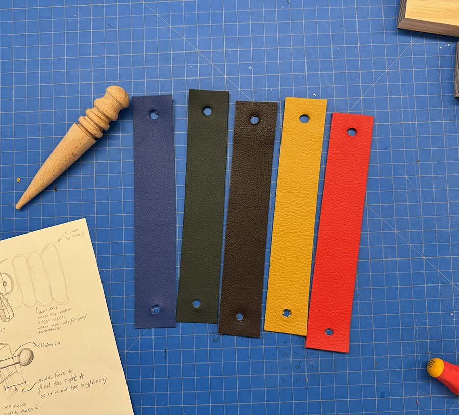
With all the pieces ready for assembly, I prepared the straps from the design. My friend Bethany very kindly gave me different colors of leather that she had and explained to me how to work with them.
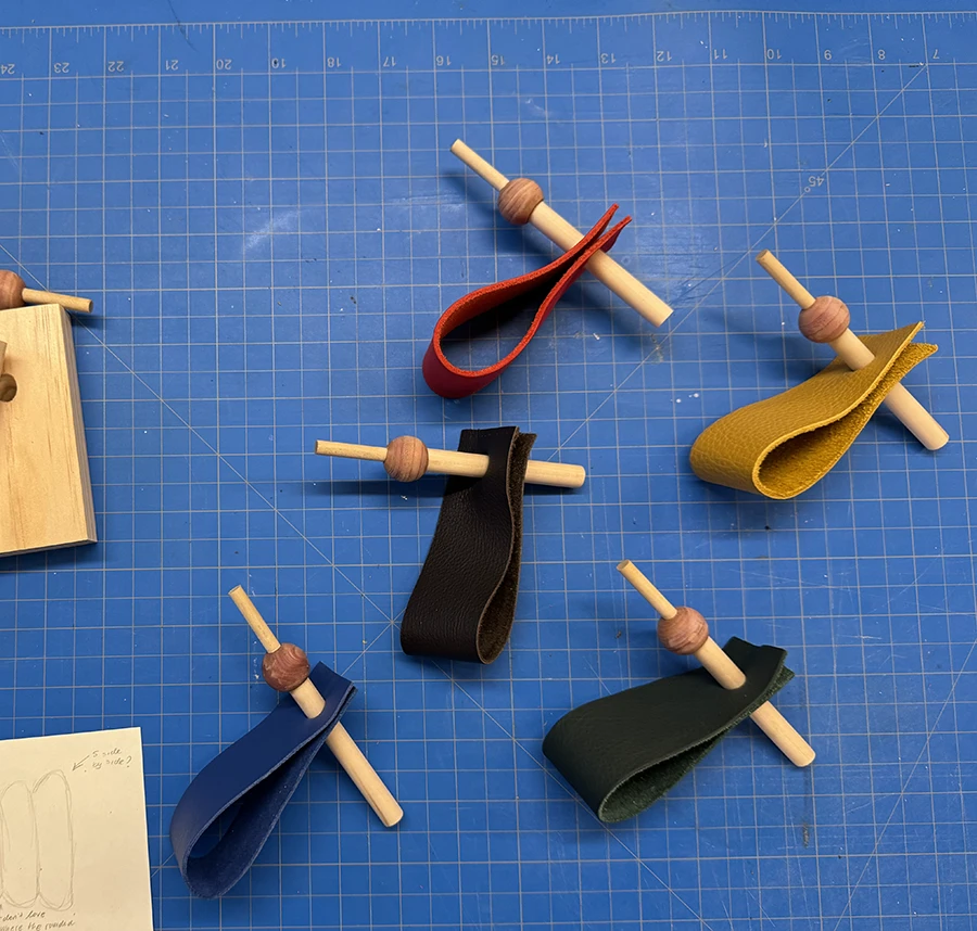
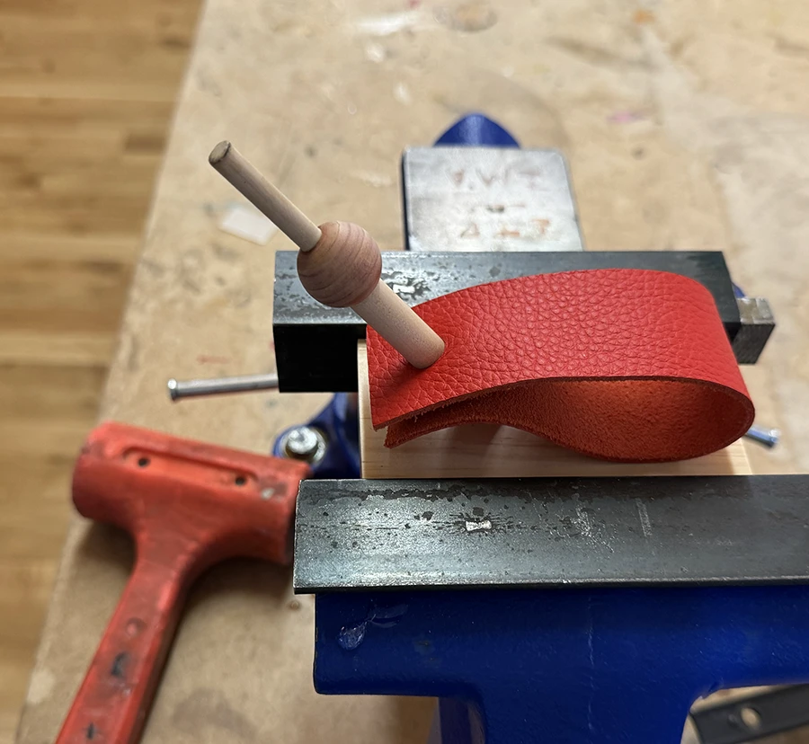
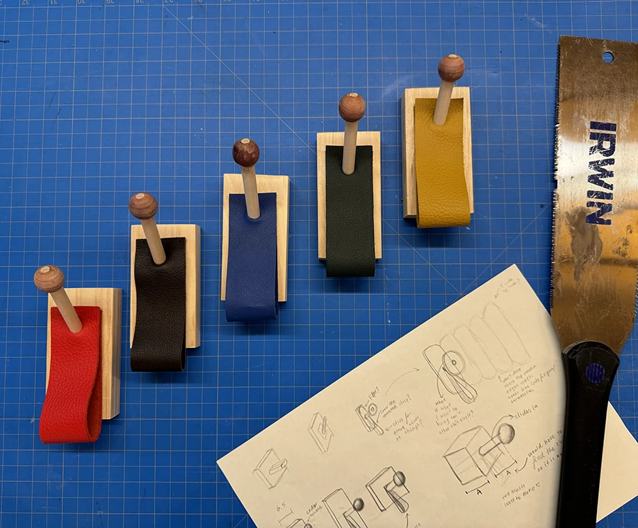
I cut the straps with a box cutter, and then made the holes, using the first hole I made as a guide for the rest of them.Then I put the dowels through the straps.I added some glue in the holes, clamped the base block down and used a mallet to hammer in the dowels. Sadly, the hole I had made was a little bit too small, so I could not push the dowels all the way to the other side, no matter how much force I used.
Lastly, I finished the hangers.
I used a saw to cut the excess dowel from the spheres.
I also sanded down the spheres after the cut, up to 400 grit, and then added some tung oil as a finish.
Week 01
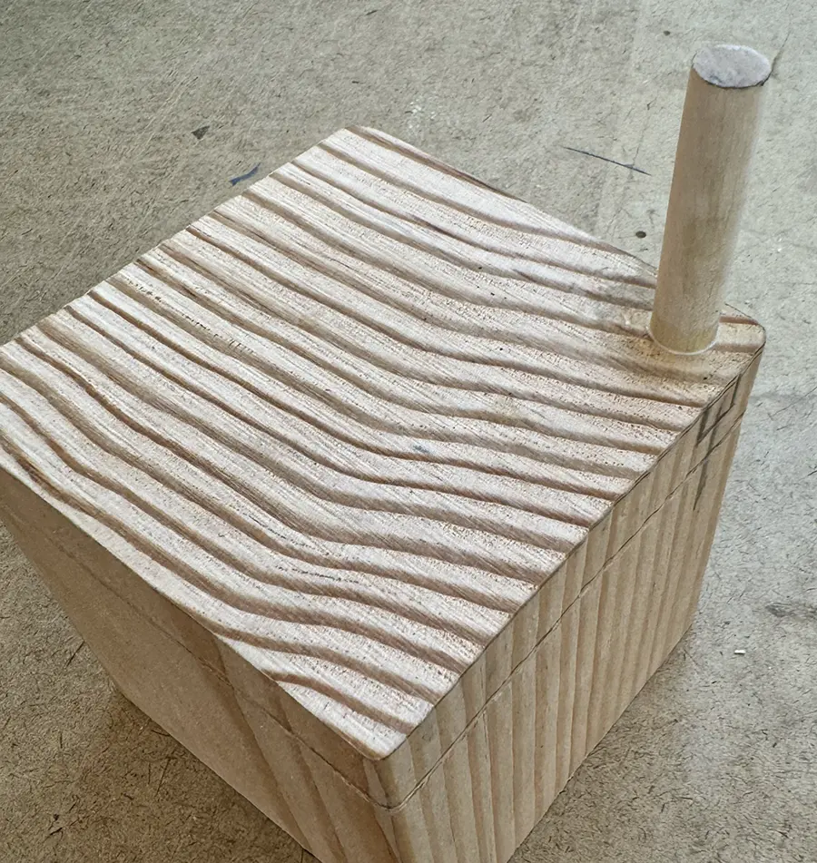
For the first week we had to make a simple box out of one piece of wood. Since this was the only assignment that didn't necessarily need to fit the chosen theme, I decided to take it as a low-stakes way to get into the groove of making while I decided what my theme for the other assignments would be.
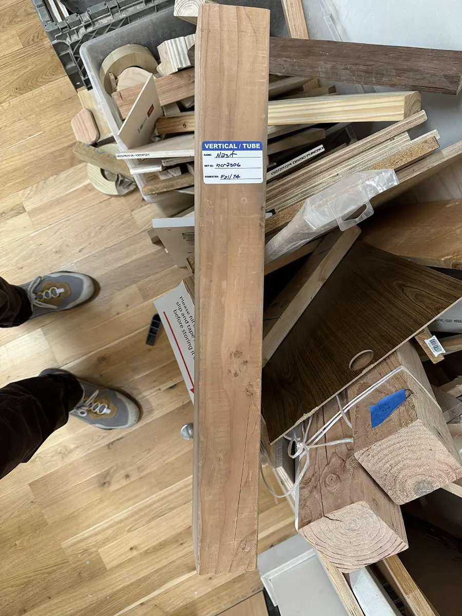
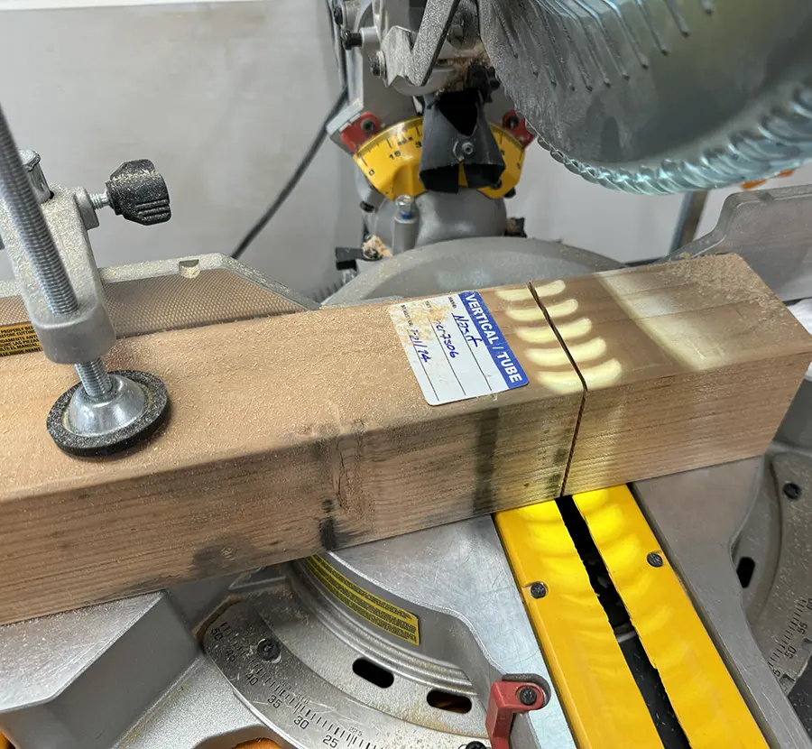
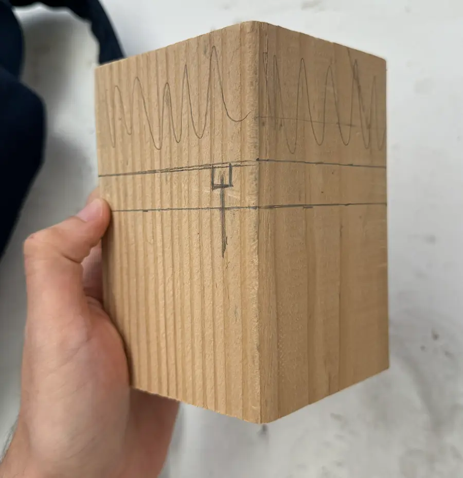
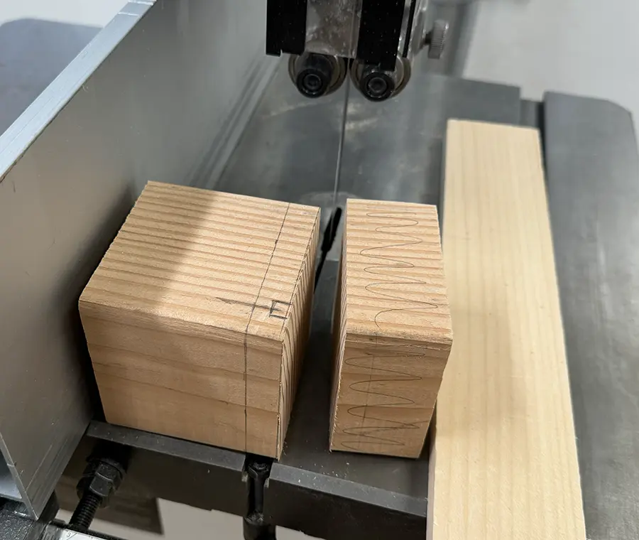
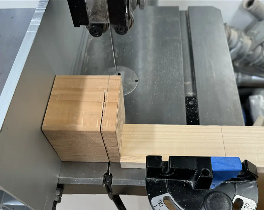
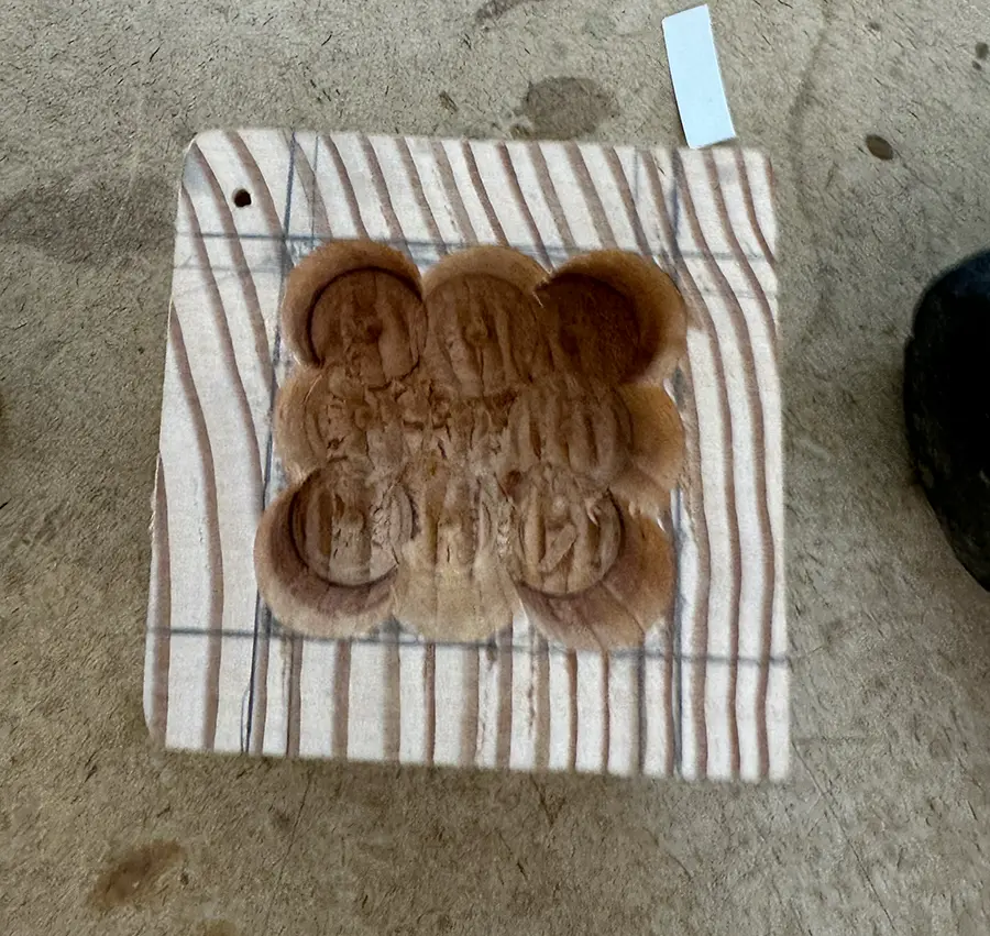
I found this long block of wood and claimed it, as it seemed that it would be really good for the wood lathe in the future.I cut a piece off the block on the compound miter saw so it would be easier to work with..Once I had this piece, I decided I really wanted my box to be more like a cube. I made some measurements and marking for the cuts and the screwhole.I cut the block once more to my desired size.
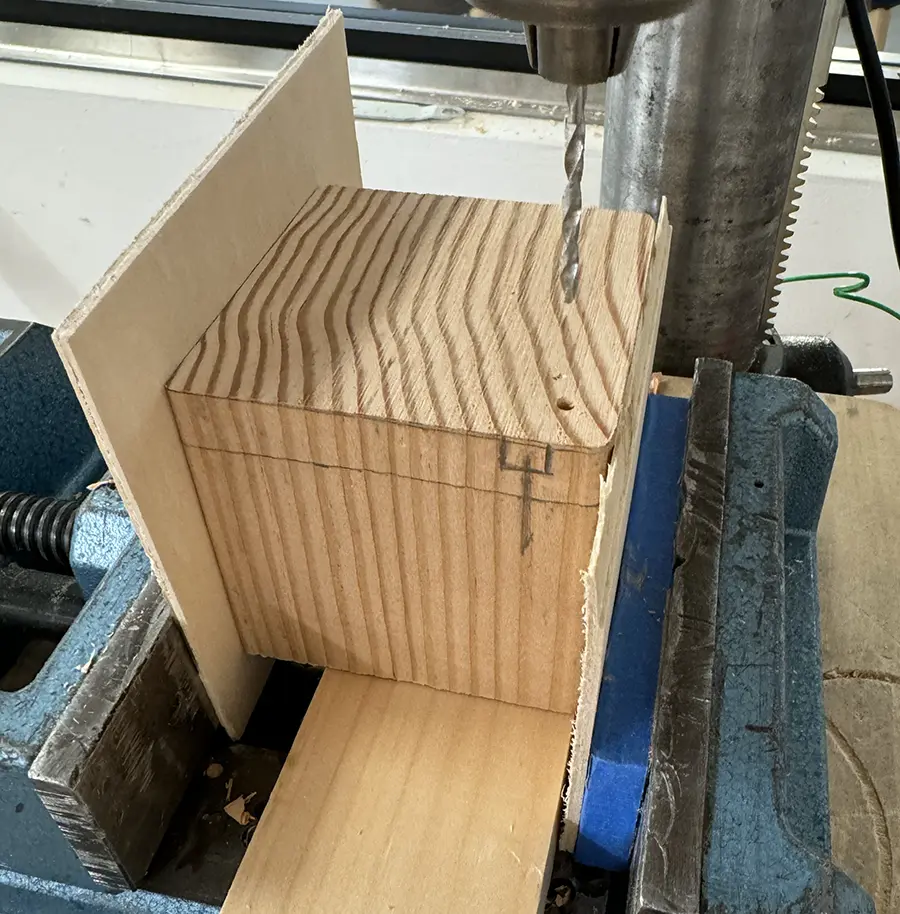
Once the block was the right size, I proceeded with the hole for the screw. I really didn't want the screw to be visible so I planned to cover it up with a wood plug.
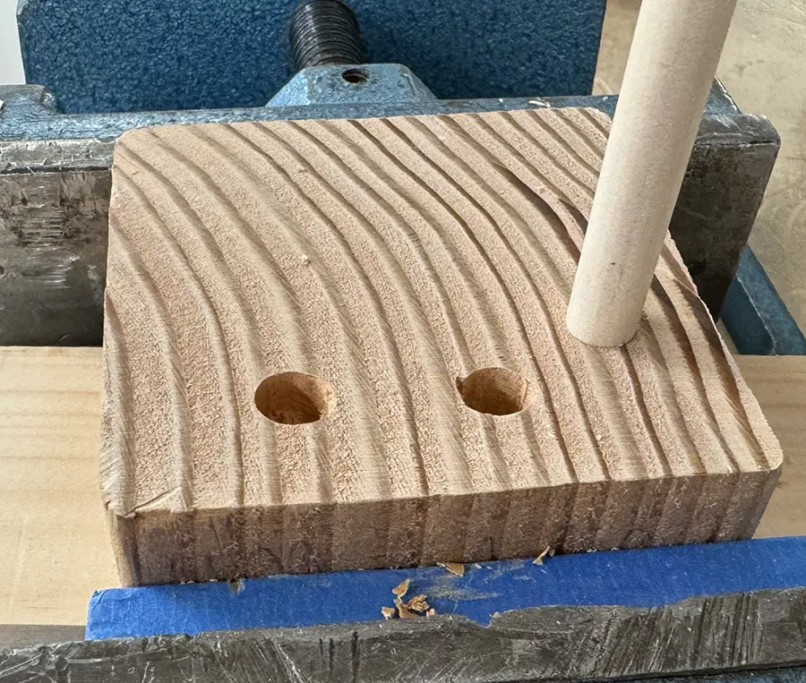
I made the deep hole for the screw to go into.I wasn't sure which drill bit size to use for my wood plug, so I tested different sizes on a scrap piece of wood until the dowel I had fit snuggly.After making the larger hole for the wood plug on my box, I cut the lid apart from the body. This operation was at first difficult, I felt I had to do too much force for it to cut. Ian instructed me to use another piece of wood to help the box keep steady as I cut, making sure no perpendicular force was being exerted on the blade.
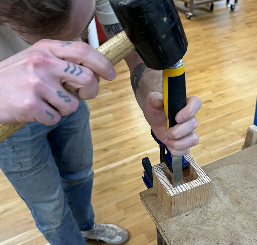
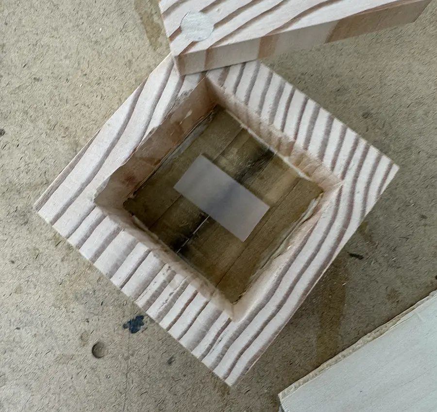
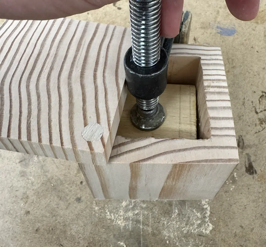
Afterwards I continued with making the cavity for my box.
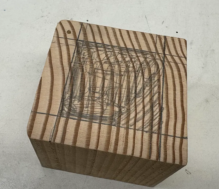
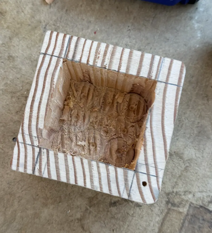
I measured and marked the size of the cavity to be removed from the box.Approximated the marked cavity with a forstner bit, using the bench press carefully to keep a consistent depth.As I was trying to even out the cavity with a chisel, my friend Niko (who has ample experience building wooden sail boats) gave me a thorough explanation of how to use the chisel.With his tips, I managed to even out the shape of the cavity to my liking.
I then added the screw to give the box its intended functionality.
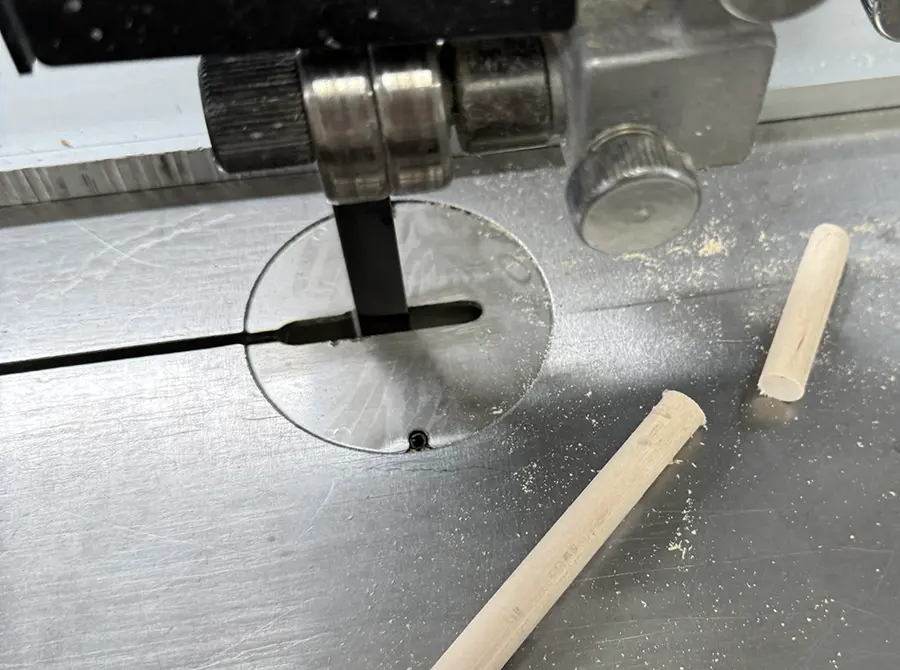
I chose a countersunk screw so it would sit as flush as possible with the bottom of the wood-plug hole.I cut the wooden dowel down to a more manageable size.After adding some wood glue, I stuck the dowel into the screw hole and let it dry overnight.Once it was dry, I used a hand saw to cut it flush with the surface.
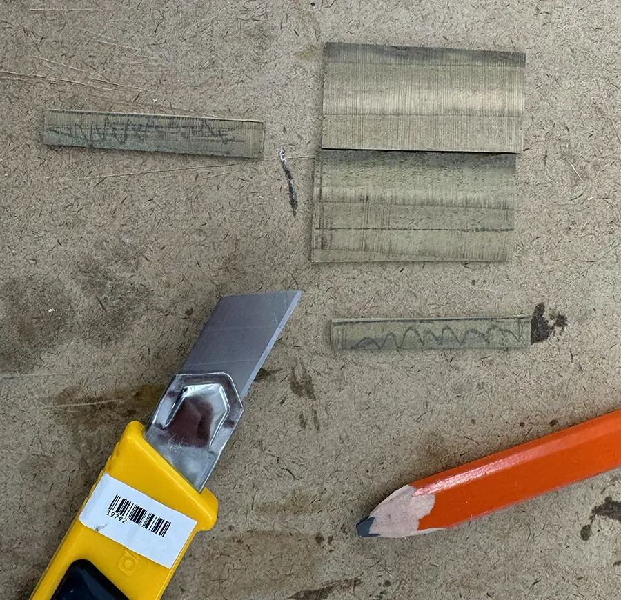
At this moment, I was a little bit bothered by the roughness of box's bottom surface, inside the cavity.
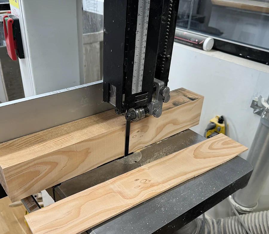
I cut some small wooden planks off some scrap wood using the band saw to test out the idea of covering the bottom of the box up. I then tried to make the same cuts with the wood I made the box out of. However, I once again was having to exert too much force in the band saw. Since Ian had already left, I decided to err on the side of caution and use the planks I had already made.I added wood glue and pasted the two planks on top of the rough bottom surface. I also placed a piece of acrylic before clamping, since I was afraid that the overflowing glue would stick to any piece of wood I added as an aid when clamping.With the help of a bigger piece of wood on top of the acrylic plank, I clamped it down and let it dry overnight.
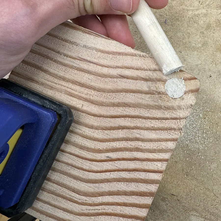
Finally, I finished my box by sanding.
The box after sanding up to 400 grit.
I also added some tung oil with a cloth and let it dry overnight.