Week 11
As we refine the idea more and more, we grow wary about time. We decided to focus initially on the listening device and push the recording device lower in the scale of importance.
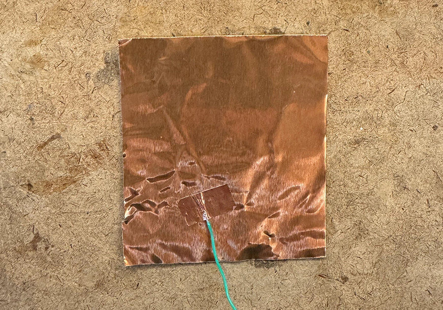
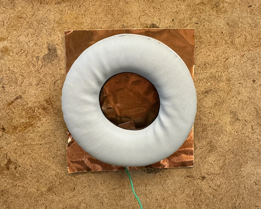
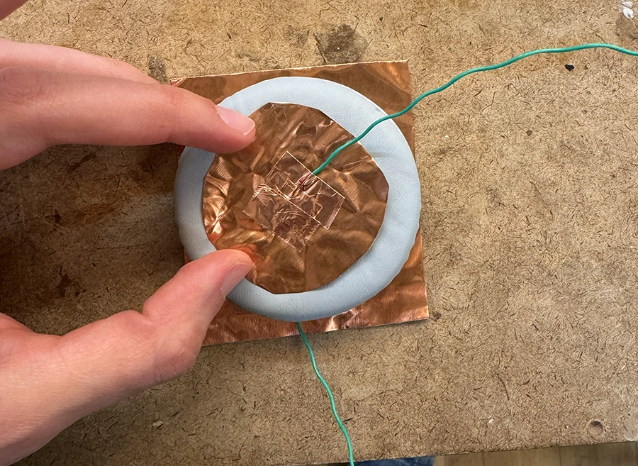
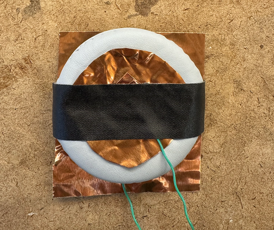
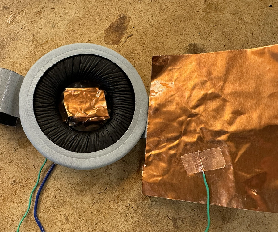
Before designing the form of the listening device, we needed to experiment with the material, to better understand how we can fabricate our own inflatables.
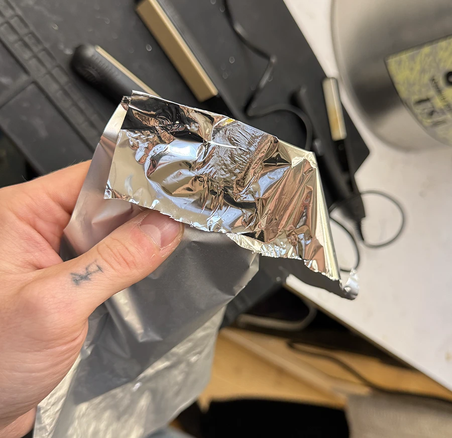
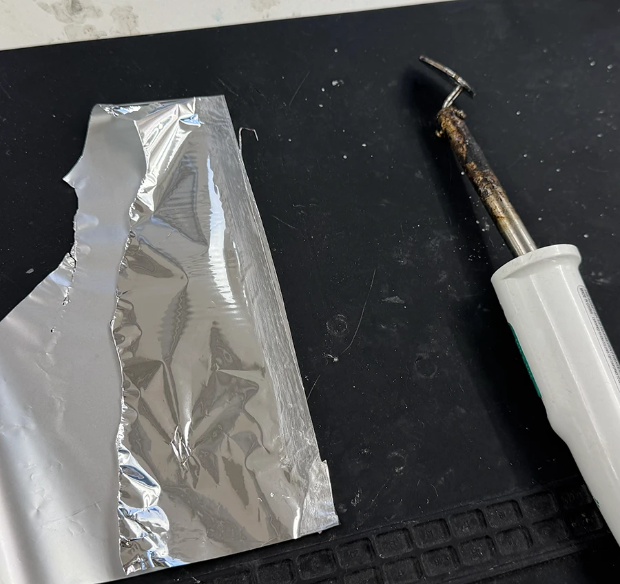

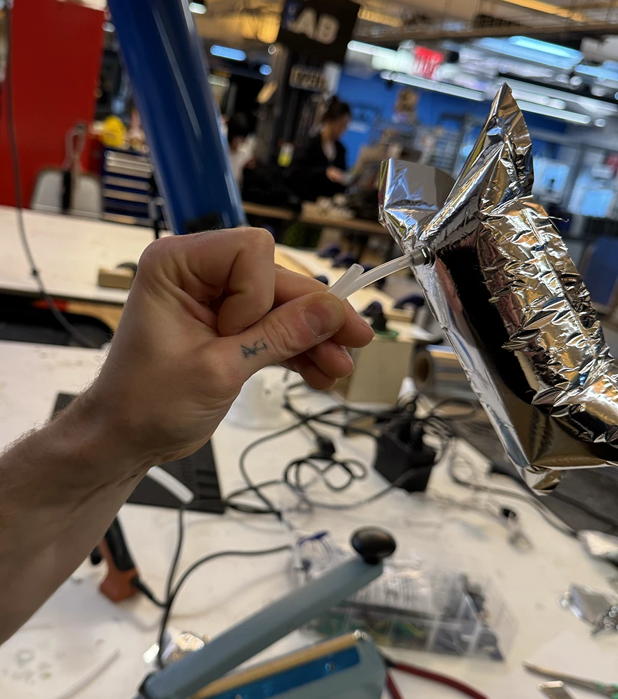
Apart from these tests, we also found some good reference information regarding how to make inflatables easily:
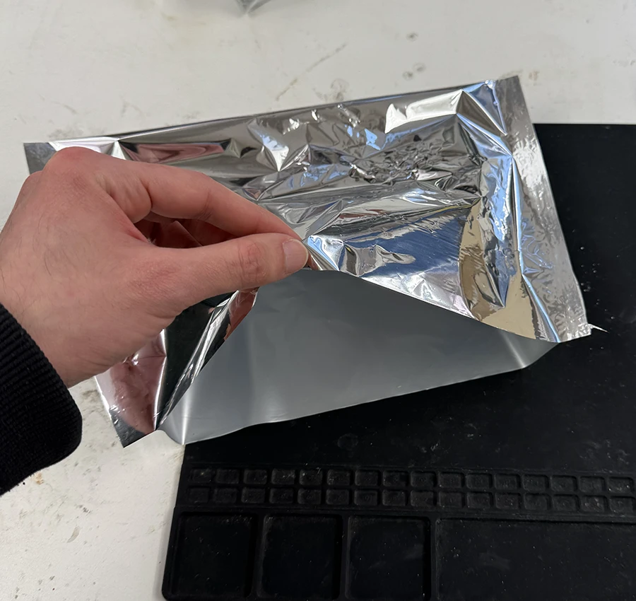
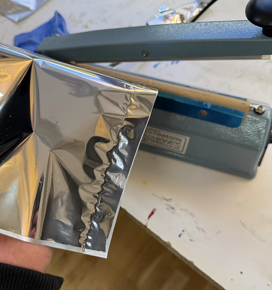
- Seaming techniques: Showcasing how seams are made in inflatable and how these impact structural strength.
- Artisanal balloon making techniques: Shows a simple way to make complex topographies in flat balloons.
Week 10
For the final, Niko and I paired up to continue exploring some concepts he began in his midterm: air as a storage medium for sound. This speculative idea explores how interacting with air can be translated to the medium of sound, like squeezing a container of air and having sound come out more quickly to simulate pressure.
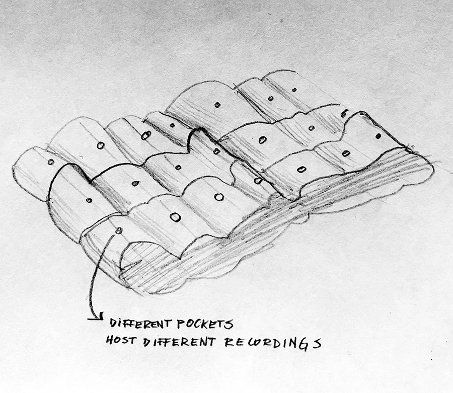
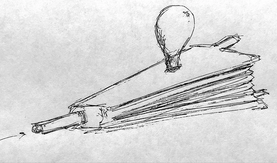
For our proposal, we looked into designing both a device to capture the sound/air as well as an output device that could provide a listening experience through gestural interactions with air receptacles:
We had a series of inspirations stemming from the following references:
- Air Structures: Book on the ways pneumatics and inflatables have been used in both artistic and industrial settings.
- Dunne & Raby's Foragers: As an inspiration on designing speculative collection devices (in our case for sound-air hybrid matter) that communicate their function visibly.
- Francis Alÿs's Samples II: In looking at how we could record a video of us collecting the sound-air samples around the city and show it as a video piece beside the interactive output device. A way of showing where it comes from.
- Tony Schwartz's Sounds of My City: The Stories, Music and Sounds of the People of New York (1956): Schwartz recorded samples of NYC over 9 years seeking to record "the audible expression of life." It is a reference of how a/this city can be collected/archived through sound.
Week 06, 07 & 08
Midterm & P5 Serial Lab
These weeks were mainly focused on working on the midterm, for which I did the arduino to p5 serial communication lab.
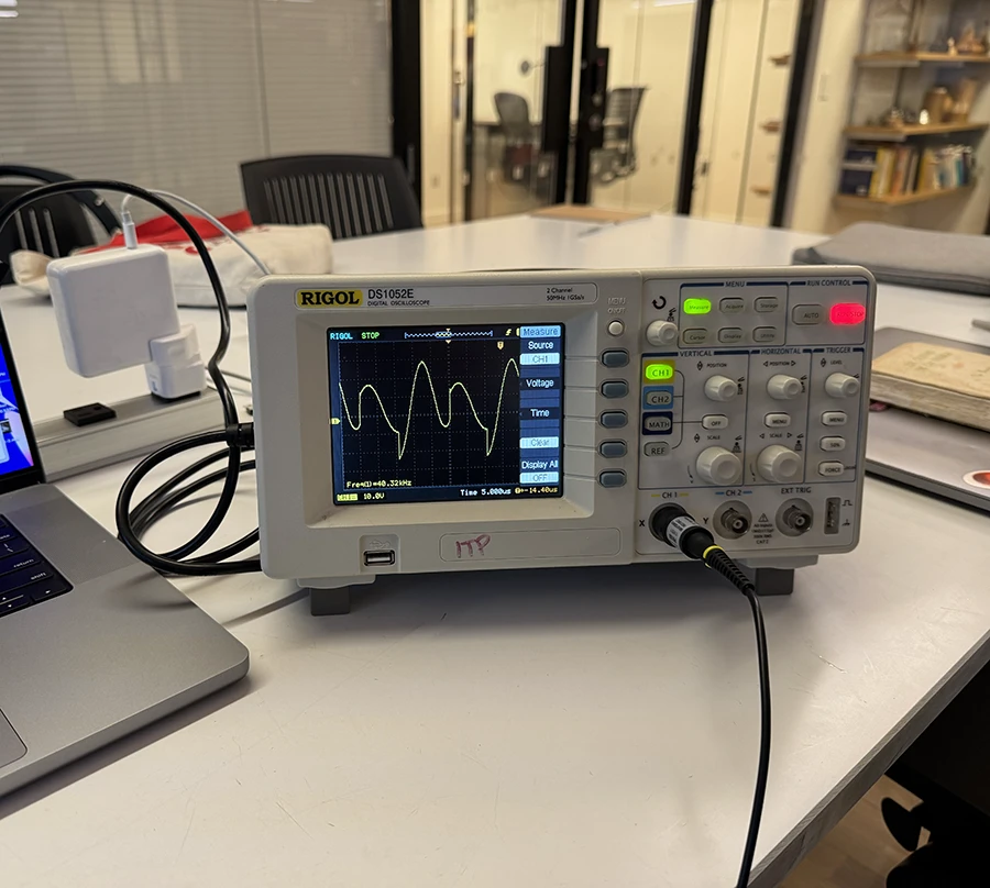
Before continuing with my project, I met with Jeff to discuss the technical questions I outlined in my previous post. Although we couldn't arrive at some definitive answers, he did show me how to use an oscilloscope to measure the frequency of the wave going to the ultrasound array, something that I must always maintain at 40kHz.
The day after, my components arrived. Sadly, I had mistaken the amount of transducers in the order, as I thought I would receive 100 but got only 1. This meant that the project would be considerably more expensive, so I decided to use Noah's speaker instead, and make a prototype of the whole system I envisioned.
The idea was to make a directional speaker that could track people in space and follow them so that only they can hear the sounds. This was part of a bigger goal of encouraging people to stand and remain close together, to hear the sounds with each other.
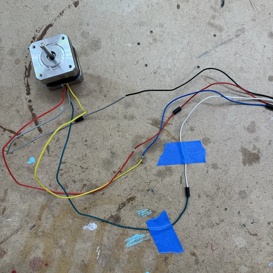
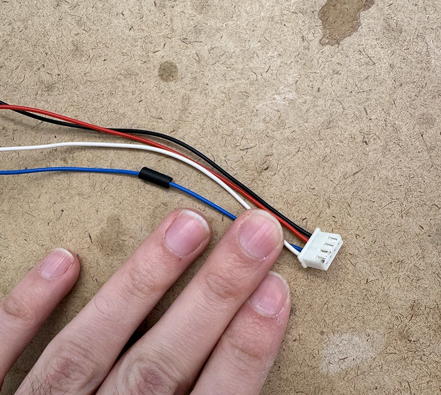
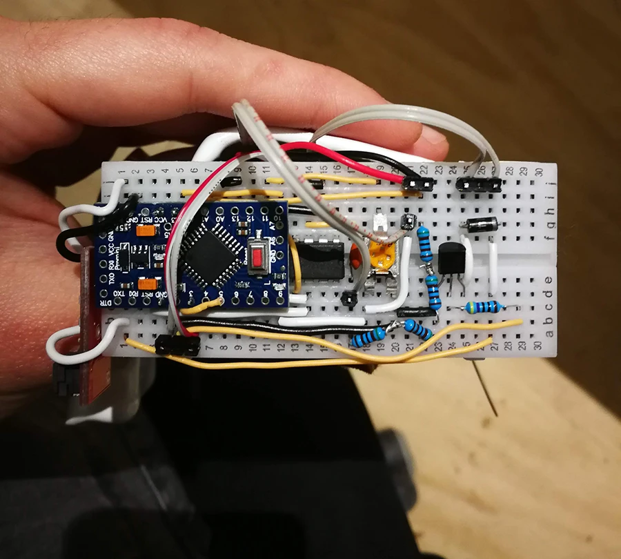
Once the motor was working, I started to work on the connection to p5.js, using the information on the lab.
The general gist of the code (which is posted below at the end of this documentation post) is that the arduino receives a byte between 0-200. From 0-99, it means it must move clockwise those amounts of steps. From 100-200, it is actually counterclockwise movement, moving the received value - 100 steps counterclockwise. This logic was built in order to send messages only using bytes and keep it speedy. When a message like this arrives, the arduino moves the motor and calculates how long it will take. During this time, it does not read any messages. Once it thinks its done, it send a message back saying it is ready for a new instruction.
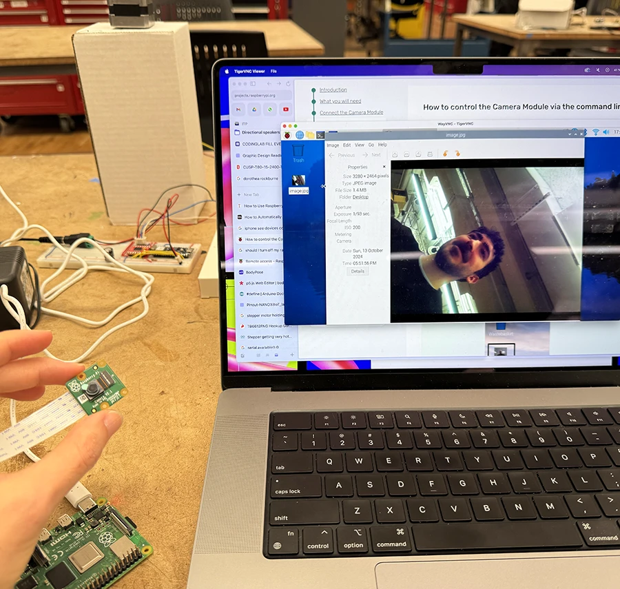
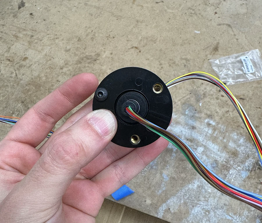
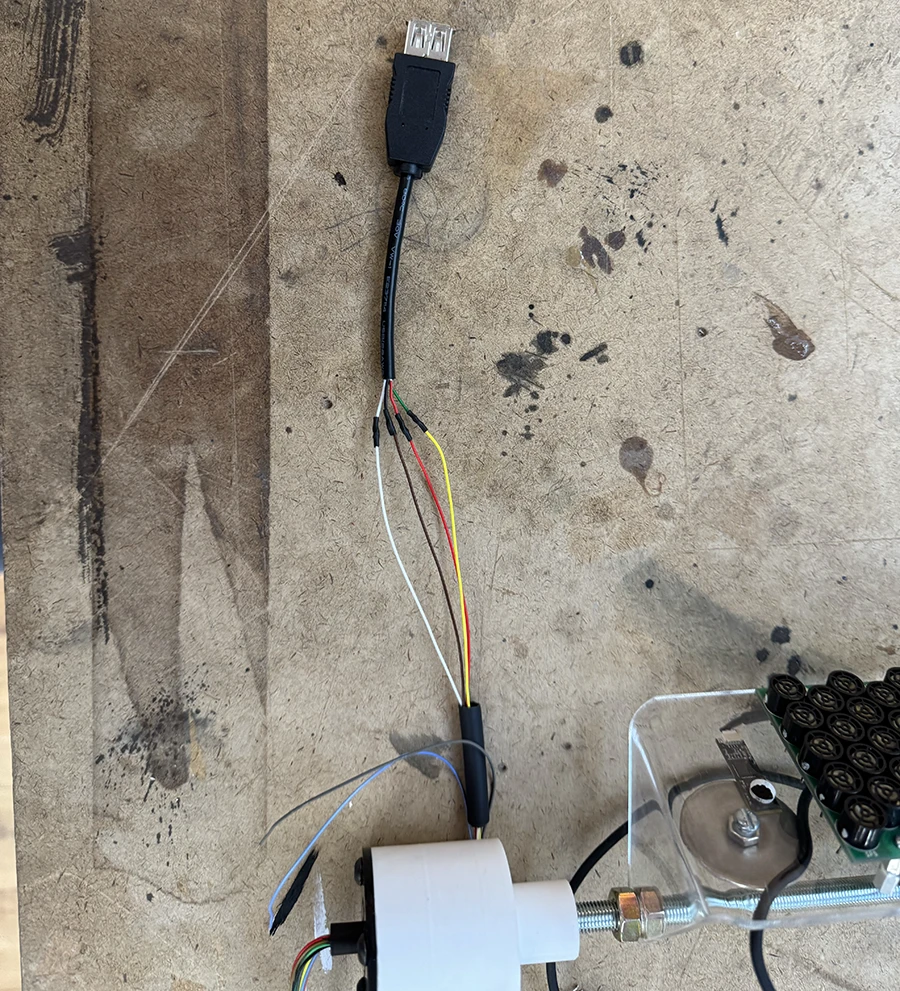
Now, in order to keep everything small, I considered running everything off of a Raspberry pi.
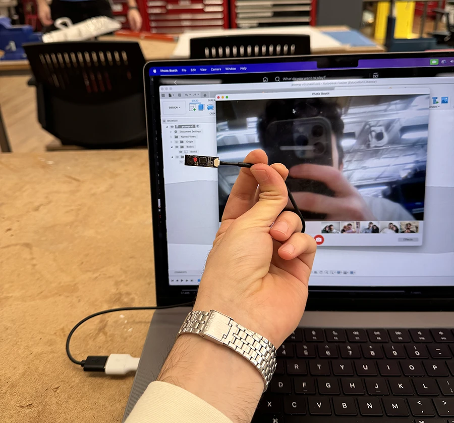
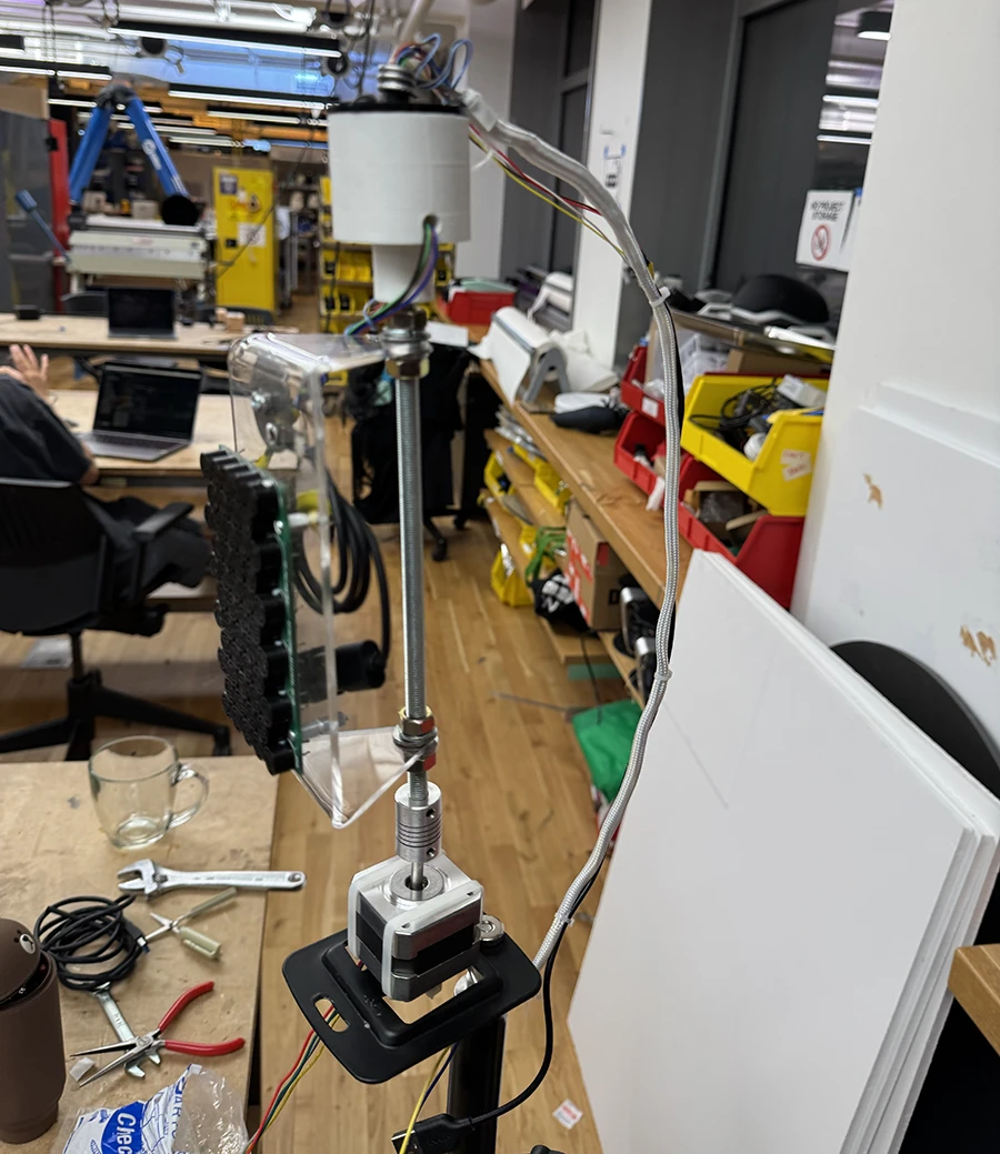
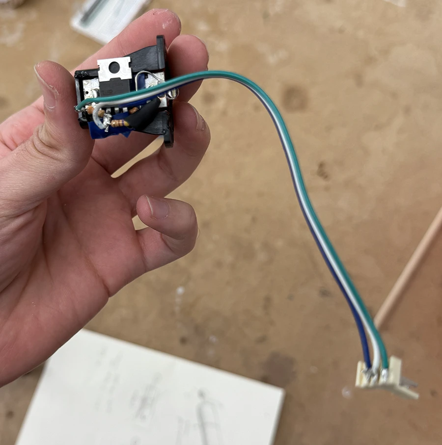
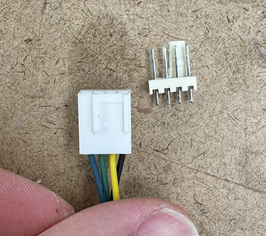
With the main technical decisions, code and electronics out of the way, I proceeded with some fabrication.
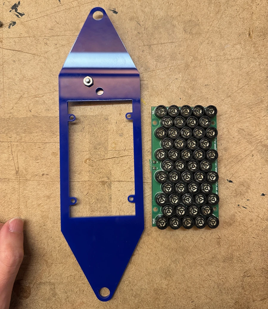
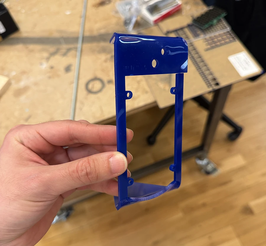
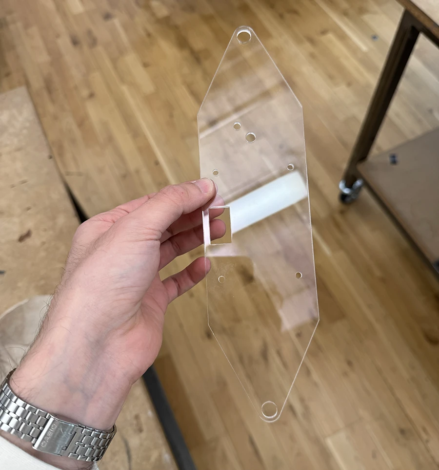
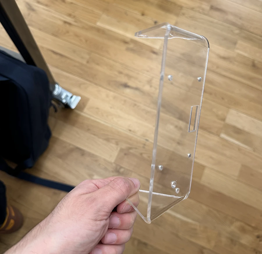
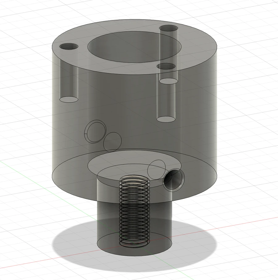
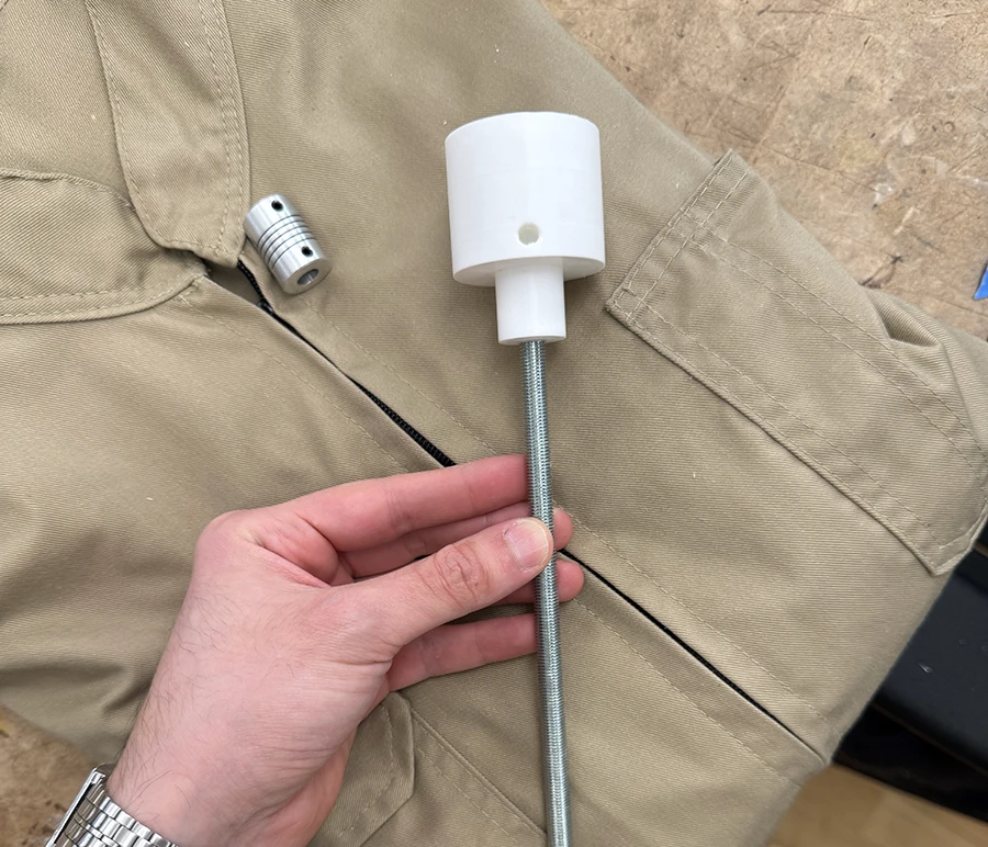
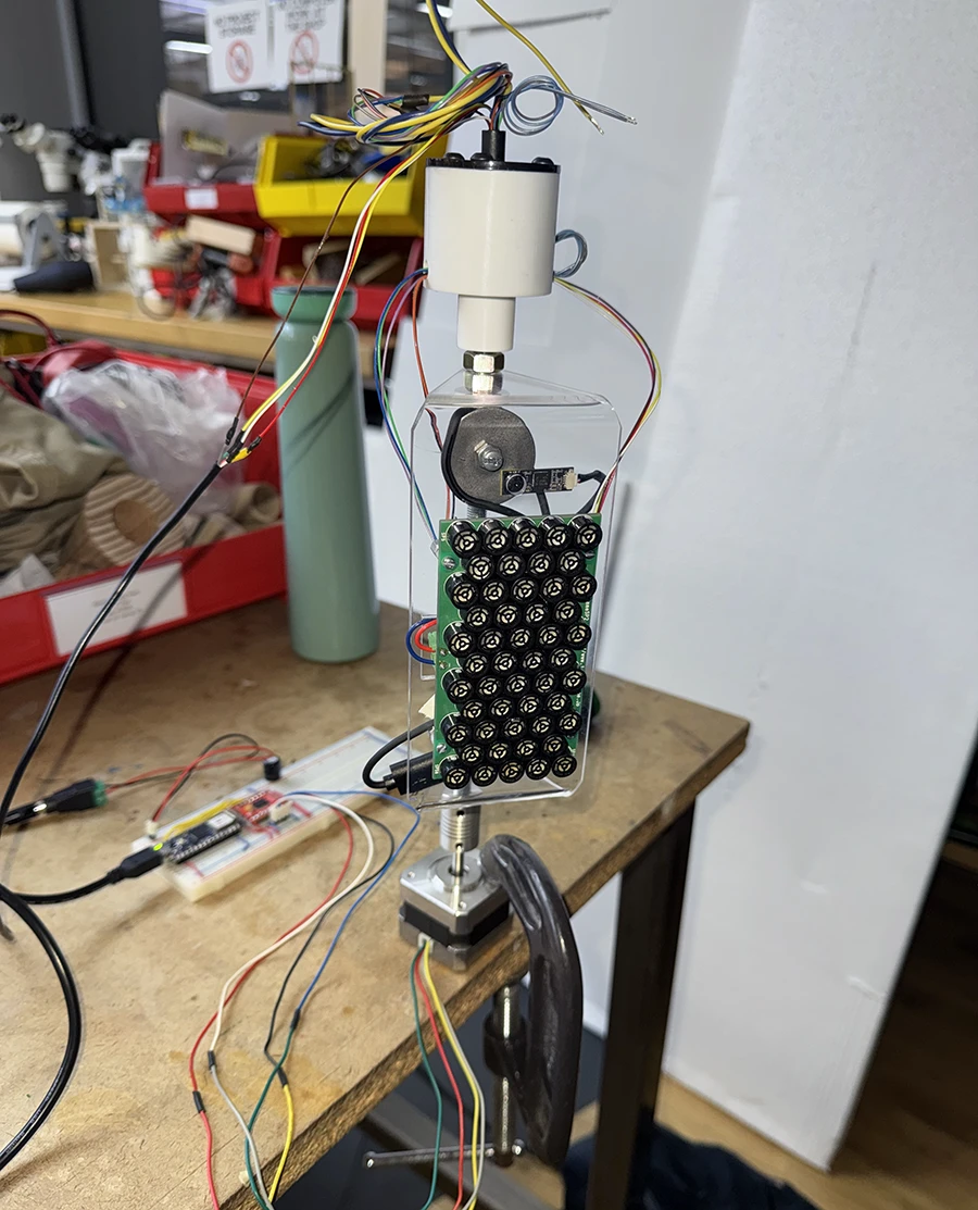
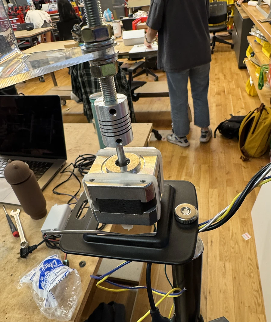
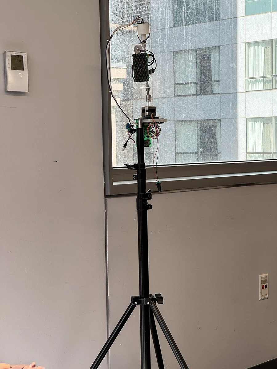
At this point, I needed to figure out how to get the mount to stand at eye level. By talking with Niko, we thought it would be a good idea to put it on top of a light stand, screwing it in using the tradition tripod screw. I found just the right tripod sized nut in the junk bin and built it up with a light stand from the ER.
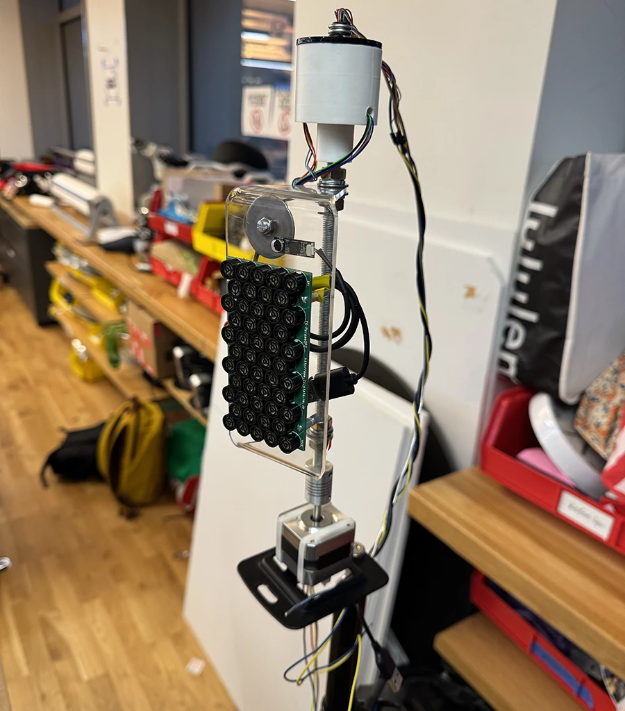
With this, the fabrication part was done. I now wanted to experiment more with the concept behind the piece and the interactions it would allow. However, time was running out :(
I built a sketch that would detect people. If it only saw one person, the motor would move away, avoiding them. If it saw more than one person, and they were close together, the motor would insted follow them. The idea being tested out was that you can only listen to the music when being together with somebody else.
Because I arrived at this late at night, there was nobody else to test it with and see how to iterate this interaction. Upon trying it in class, it became apparent that it was too much of a complex interaction, and the users would not really understand what was going on. Danny suggested to keep looking into it, that maybe the speaker following single people would be necessary at the beginning, and then this behaviour could shift as more people come into the scene.
Show/hide Arduino code below
#include <Stepper.h>

//Motor
const int standbyPin = 7; //Set low when motor is idle to lower temperature. May affect holding torque
const int stepsPerRevolution = 200; //Defined by the motor
const int stepperRPM = 50;
const int stepsPerMs = stepsPerRevolution * stepperRPM / 60000;
bool busy = false; //Is the motor currently doing an instruction it received
unsigned long jobStart = 0; //When did the current job start (ms, from millis())
int jobLength = 0; //How many ms will the current job take

Stepper myStepper(stepsPerRevolution, 8, 9, 10, 11);

void setup() {
    // set the speed at 50 rpm:
    myStepper.setSpeed(stepperRPM);

    //Initialize the standby pin
    pinMode(standbyPin, INPUT);
    digitalWrite(standbyPin, HIGH);

    // initialize the serial port:
    Serial.begin(9600);
}

void loop() {
    //When a message from p5 is received
    if (Serial.available() > 0 && !busy) {
    // read the incoming byte:
    int inByte = Serial.read();

    //If it is a non-zero movement message
    if (inByte <= 200 && inByte != 0) {
        updatePosition(inByte); //Move motor to new position
    } else {
        informState(); //Inform that the motor is available
    }
    }

    checkCurrentState(); //Check if the motor is doing a job and update variable 'busy'
}

void updatePosition(int steps) { //Move motor
    if (steps <= 100) {
    //From 1 to 100 the steps are counterclockwise
    steps *= -1;
    } else {
    //From 101 to 200, the steps are actually 1-100 clockwise
    steps -= 100;
    }

    //Connect the motor
    //digitalWrite(standbyPin, HIGH);
    //Take the instructed steps
    myStepper.step(steps);
    busy = true;
    jobStart = millis();
    //Still need to figure out how to calculate this correctly
    //jobLength = ceil(abs(steps)/stepsPerMs);
    jobLength = 10;
}

void informState() {
    //Send the current state to p5
    Serial.write(busy);
}

void checkCurrentState() {
    if ( busy ) {
    //If estimated job duration time has passed
    if ( millis() - jobStart > jobLength) {
        //Set at not busy
        busy = false;

        //Disconnect motor
        //digitalWrite(standbyPin, LOW);

        informState();
    } else {
        busy = true;
    }
    }
}
Show/hide p5.js code below
const serial = new p5.WebSerial();

let inData = 0;
let portButton;

//ml5 setup
let video;
let bodyPose;
let poses = [];
let centers = [];
// let connections;

let captureAvailable = false;

const globalConfidence = 0.1;

let song;

function preload() {
    // Load the bodyPose model
    bodyPose = ml5.bodyPose( {flipped: true});
    song = loadSound('assets/merry-go-round.mp3');
}


function setup() {
    createCanvas(640,480);
    // check to see if serial is available:
    if (!navigator.serial) {
    alert("WebSerial is not supported in this browser. Try Chrome or MS Edge.");
    noLoop();
    return;
    }
    startSerial();

    navigator.mediaDevices.enumerateDevices().then(function(devices) {
    devices.forEach(function(device) {
        if (device.label.includes('USB 2.0 PC Cam')) {
        const constraints = {
            video: {
                deviceId: device.deviceId
            },
            audio: false,
            flipped: true,
            };

            video = createCapture(constraints);
            video.elt.addEventListener('end', function(){
            console.log("Video stream ended, attempting to reconnect...");
            });
            video.size(640, 480);
            video.hide();
            bodyPose.detectStart(video, gotPoses);
            // Get the skeleton connection information
        //   connections = bodyPose.getSkeleton();
            captureAvailable = true;
        }
    });
    });
}

function draw() {
    background(255);
    if (!song.isPlaying()) {
        song.play();
    }
    // Draw the webcam video
    if(captureAvailable) {
        image(video, 0, 0, width, height);

        // Draw all centers;
        if(centers.length > 0) {
            centers.forEach(center => {
                noFill();
                stroke(0,255,0);
                line(center, 0, center, height);
            });
        }

        //Draw the distance between each person
        let orderedCenters = centers.slice();
        orderedCenters.sort((a, b) => a - b);
        for( let i = 0; i<orderedCenters.length; i ++) {
        if( i+1 < orderedCenters.length ){
            fill(0,255,0);
            const closestDistance = orderedCenters[i+1] - orderedCenters[i];
            if(closestDistance < proximity) {
                fill(0,0,255);
                stroke(0,0,255);
            }
            textAlign(CENTER);
            text(orderedCenters[i+1] - orderedCenters[i], orderedCenters[i] + (orderedCenters[i+1] - orderedCenters[i])/2, height/2 - 20);
            line(orderedCenters[i], height/2, orderedCenters[i+1], height/2);
        }
        }
    }else {
        textAlign(CENTER);
        text('External camera unavailable or loading :(', width/2, height/2);
    }

    //Draw audible area
    fill(220, 40);
    noStroke();
    rect( (width - audioRange)/2, 0, audioRange, height );
}

function gotPoses(results) {
    // Save the output to the poses variable
    poses = results;

    centers = [];
    //Run through poses and get the centers
    for (let i = 0; i < poses.length; i++) {
        let person = poses[i];
        let center = false;
        if(person.nose.confidence > globalConfidence){
            center = person.nose.x;
        }else if(person.right_eye.confidence > globalConfidence && person.left_eye.confidence > globalConfidence){
            center = person.right_eye.x - person.left_eye.x;
            const person_span = person.right_eye.x - person.left_eye.x;
            center = person.left_eye.x + person_span/2;
        }else if(person.right_shoulder.confidence > globalConfidence && person.left_shoulder.confidence > globalConfidence){
            center = person.right_shoulder.x - person.left_shoulder.x;
            const person_span = person.right_shoulder.x - person.left_shoulder.x;
            center = person.left_shoulder.x + person_span/2;
        }else {
            let minX = Infinity;
            let maxX = -Infinity;
            person.keypoints.forEach(keypoint => {
                if(keypoint.confidence > 0.1) {
                    minX = min(minX, keypoint.x);
                    maxX = max(maxX, keypoint.x);
                }
            });
            const person_span = maxX - minX;
            center = minX + person_span/2;
        }

        if(center !== false ){
            centers.push(center);
        }
    }


    if( centers.length > 0 ){
        // targetPos = map(width/2 - centers[0], -width/2, width/2, 3, -3, true); //distance from center of screen to center of person
        // if(Math.abs(Math.floor(targetPos)) == 1) {
        //     targetPos = 0;
        // }

        if(centers.length >= 2){
            const closestPair = findClosestPair(centers);
            if( Math.abs(closestPair[0] - closestPair[1]) < proximity ) {
                follow(closestPair[0]);
            }
        }else {
            avoid();
        }
    }
}

let audioRange = 140;

function avoid() {
    for (const person of centers) {
        if(person > (width - audioRange)/2 && person < (width + audioRange)/2) {
            targetPos = random(-20, 20);
            console.log('avoided');
            break;
        }
    }
}

let proximity = 70;

function follow( coord ){
    targetPos = map(width/2 - coord, -width/2, width/2, 3, -3, true); //distance from center of screen to center of person
    console.log('followed');
}

function findClosestPair(arr) {
    if (arr.length < 2) {
        return null; // Not enough numbers to compare
    }

    // Step 1: Sort the array in ascending order
    arr.sort((a, b) => a - b);

    // Step 2: Initialize variables to track the closest pair and the smallest difference
    let minDiff = Infinity;
    let closestPair = [];

    // Step 3: Iterate through the sorted array to find the smallest difference
    for (let i = 1; i < arr.length; i++) {
        let diff = Math.abs(arr[i] - arr[i - 1]);

        if (diff < minDiff) {
        minDiff = diff;
        closestPair = [arr[i - 1], arr[i]];
        }
    }

    return closestPair;
    }

function startSerial() {
    // if serial is available, add connect/disconnect listeners:
    navigator.serial.addEventListener("connect", portConnect);
    navigator.serial.addEventListener("disconnect", portDisconnect);
    // check for any ports that are available:
    serial.getPorts();
    // if there's no port chosen, choose one:
    serial.on("noport", makePortButton);
    // open whatever port is available:
    serial.on("portavailable", openPort);
    // handle serial errors:
    serial.on("requesterror", portError);
    // handle any incoming serial data:
    serial.on("data", serialEvent);
    serial.on("close", makePortButton);
}

/* SERIAL CALLBACK FUNCTIONS */

// if there's no port selected,
// make a port select button appear:
function makePortButton() {
    // create and position a port chooser button:
    portButton = createButton("choose port");
    portButton.position(10, 10);
    // give the port button a mousepressed handler:
    portButton.mousePressed(choosePort);
}

// make the port selector window appear:
function choosePort() {
    if (portButton) portButton.show();
    serial.requestPort();
}

// open the selected port, and make the port
// button invisible:
function openPort() {
    // wait for the serial.open promise to return,
    // then call the initiateSerial function
    serial.open().then(initiateSerial);

    // once the port opens, let the user know:
    function initiateSerial() {
        console.log("port open");
        serial.print(201);
    }
    // hide the port button once a port is chosen:
    if (portButton) portButton.hide();
}

// pop up an alert if there's a port error:
function portError(err) {
    alert("Serial port error: " + err);
}
// read any incoming data as a string
// (assumes a newline at the end of it):
let targetPos = 0;
let timeoutIndex = null;

function serialEvent() {
    inData = Number(serial.read());
    //console.log(inData);

    //Available for moving motor
    if(inData == 0 ) {
        clearTimeout(timeoutIndex);

        setTimeout( function(){
            let dataToSend = Math.floor(targetPos);
            if( dataToSend < 0 ){
                dataToSend = abs(dataToSend);
                dataToSend += 100;
            }
            if(dataToSend != 0 ){
                //console.log(dataToSend);
            }

            //console.log(dataToSend);

            serial.print(dataToSend);
            targetPos = 0;
        }, 100);

    }//else, it is busy, wait for the 0.
}

// try to connect if a new serial port
// gets added (i.e. plugged in via USB):
function portConnect() {
    console.log("port connected");
    serial.getPorts();
}

// if a port is disconnected:
function portDisconnect() {
    serial.close();
    console.log("port disconnected");
}

function closePort() {
    serial.close();
}
Week 05
Midterm
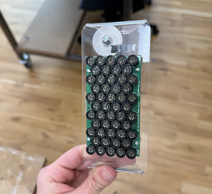
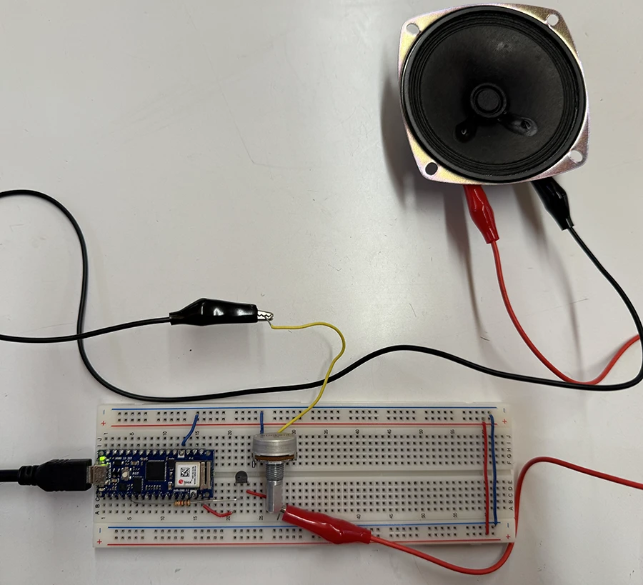
This week I continued researching about parametric speakers, trying to best understand their limitations and their possibilites. I started testing them out with the one Noah lent me:
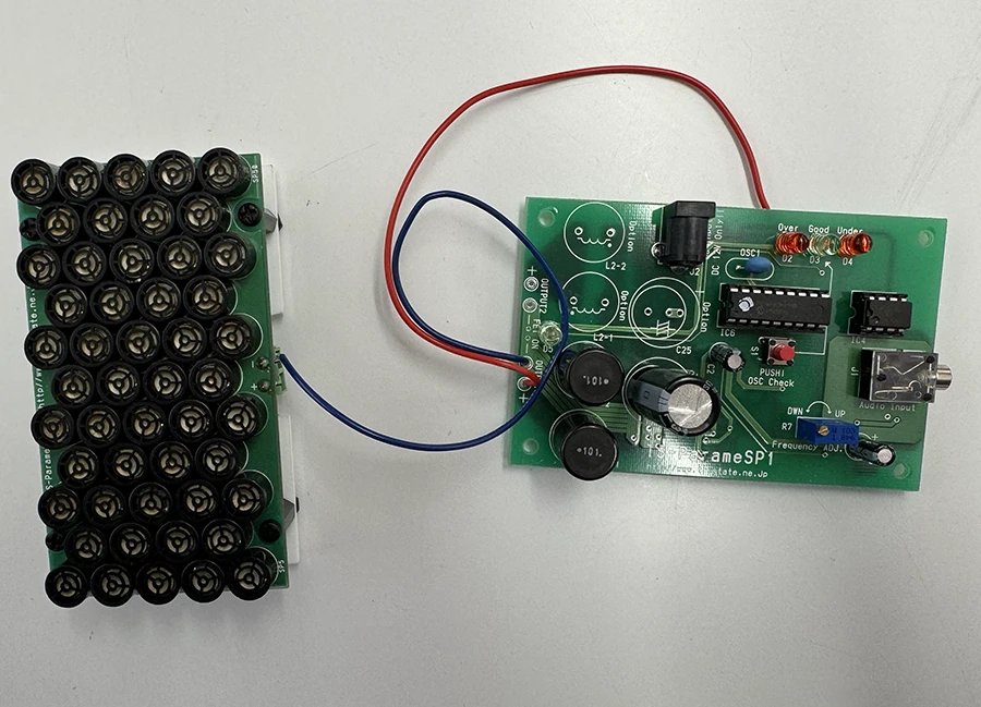
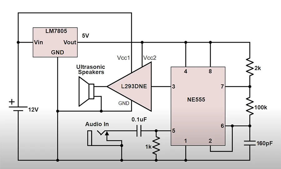
I also studied the technical aspects of this technology and drew a few important conclusions:
- They seem to work best from a distance, so mounting them from an unreachable place is best. Ceiling mount might be the ideal location.
- These speakers (with the circuits I have found) cannot transmit very high or very low frequencies (about 400Hz to 5KHz), which is very important to take into account when deciding the sounds to be played. Maybe they could be accompanied with a non-directional bass, so only the melody is projected directionally.
- The ideal frequency to modulate the ultrasound at is 60KHz, however the only affordable transducers I could find are 40KHz ones. It seems that the main industrial manufacturers like Holosonics use 60KHz.
- More transducers per array translate to more directionality (a more closed angle).
- They are very reflective, it might be a good idea to use them in a sound-isolated space than can absorb the waves.
- There are some worries about the safety of this technology. The general consensus is that ultrasound applications should not exceed 110-115dB SPL (sound pressure levels) to remain safe. This is orders or magnitude above what these hand built transducers can do, but it is good to keep in mind.
A lot of this information came from a translated version of the speaker's documentation, other japanese documentation, the first comment on an instructables video, and the Wikipedia article about generating sound from Ultrasound.
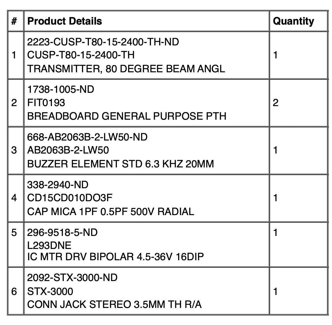
I prepared a BOM and ordered the required components from DigiKey:
Next steps will be building the prototype and meeting with some faculty to go over some of the technical questions I have.
Labs
This week's labs focused on controlling high loads using transistors and relays. This is something I have worked on before, but I can never seem to memorize what each leg of the mosfet does. So I decided to review it by making a simple analog circuit.
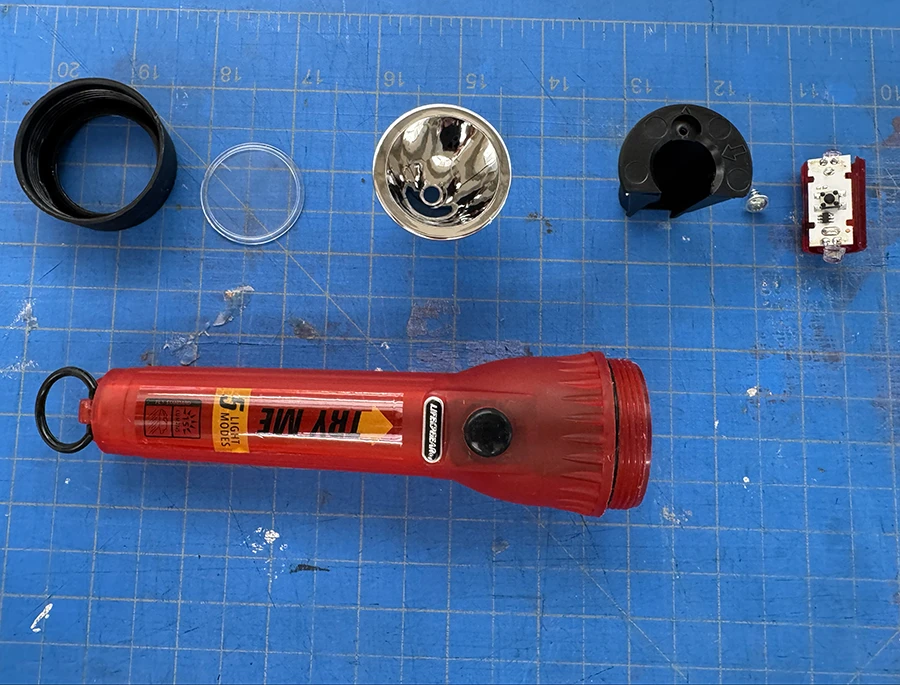
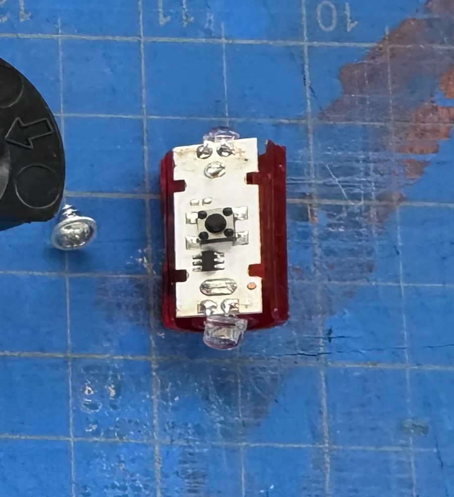
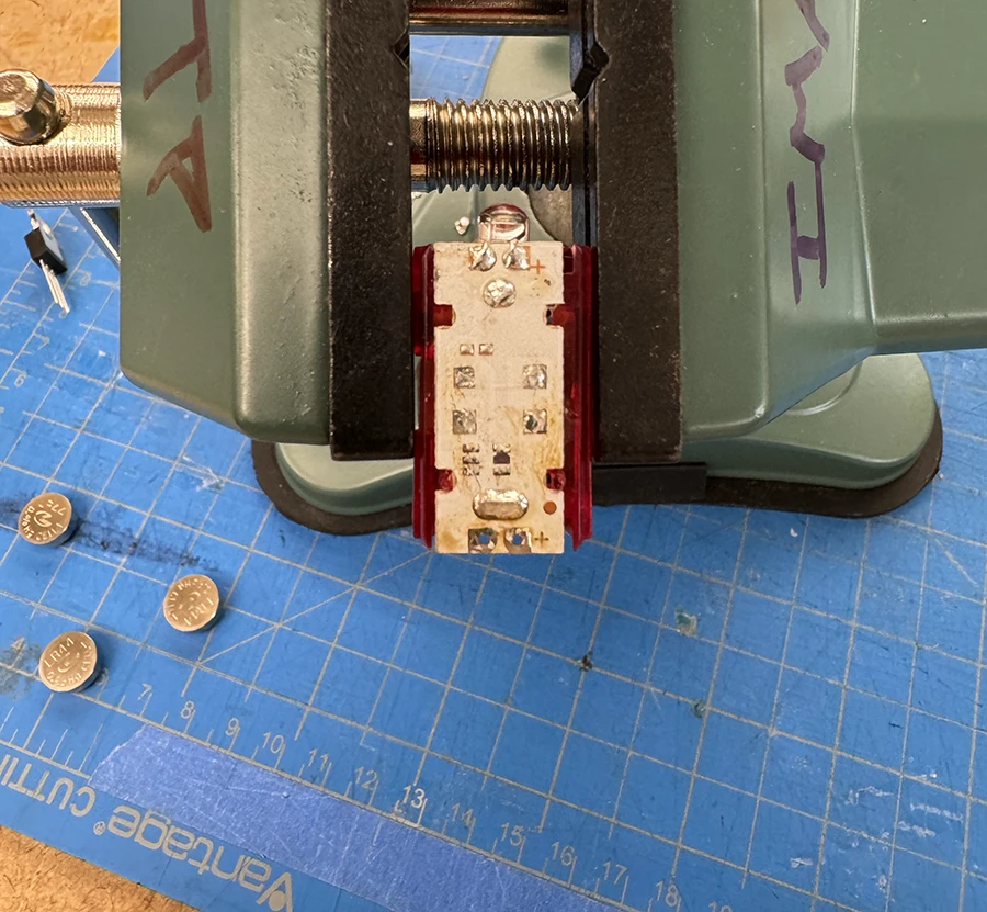
For my intro to fabrication, I wanted to make a flashlight that was dimmable, so I bought a premade flashlight and modified its circuit using a mosfet:
Week 04
This week was mainly focused on finding a concept for the midterm, apart from the course readings. After looking into the midterm project description, I found the idea of doing a research project the most appealing, exploring technologies I have not worked with before for a future (possibly final project) piece.
For a long time, I have been interested in directional speakers: sound transducers that project sound in a narrow beam, so only those in the trajectory of said beam can hear it. Normally, these speakers, like the ones from Focusonics or SRAY are very expensive.
However, recently I have come across a low-cost way to build these speakers:
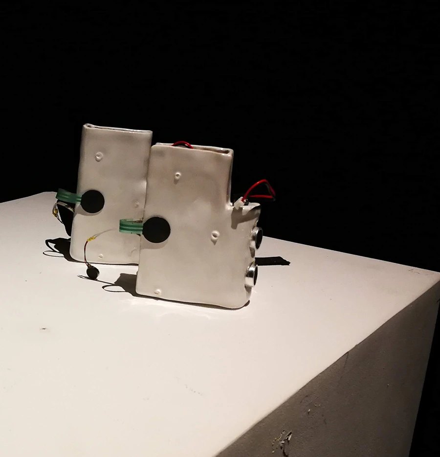
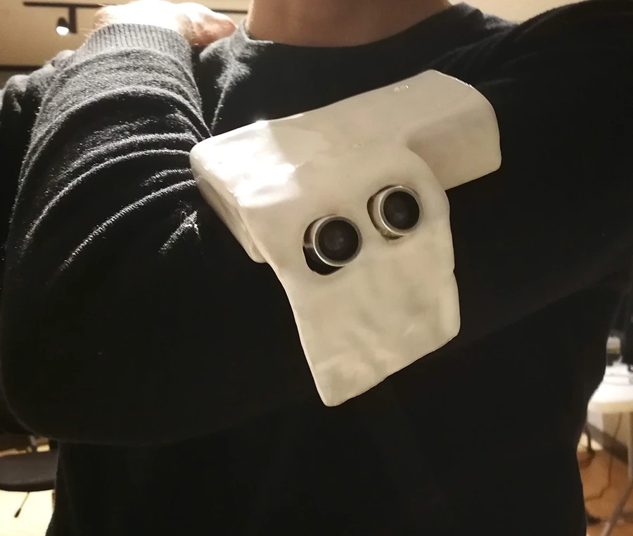
I have worked with these transducers on their own somewhat before, making kind of like an ultrasonic radio, to send private messages over-the-air and sense them through haptics. In retrospect it was very ill-considered. It was an exploration on haptic commmunication, but the directionality of ultrasound did not really help: the two devices had to be pointed directly at each other. The mount design and material were not ideal either.
So I would really enjoy revisiting this directionality of ultrasound through a new lens, which is why I am looking to focus my midterm on building and researching directional "spotlight" speakers.
A longer term goal is to implement these speakers in an automated system, that can actually point and project audio at specific people around it. To do this, I would also like to explore Servo Pan/Tilt Brackets and stepper motor traveling nut linear actuators, as potential ways to control my system.
Some art pieces that explore/exploit these phenomenons:
Week 03
This week's work was focused on analog signals, specifically working with some audio and motors. Since I have experience working with motors, but very little with audio, I decided to focus more on that.
I was intrigued by the Mozzi sound synthesis library mentioned in the lab readings. At first I really couldn't believe something like that existed without the need of a shield or an extra breakout board. So I decided to try it out.
Once I had tested that out with a simple tone, I went ahead and uploaded an example from the library.
I then started moving the code around and making some changes, trying to understand how it all works. Since I don't have much experience with sound, some large concepts were not very clear to me. I spent a good time reading and fiddling with the Mozzi online learning guides.
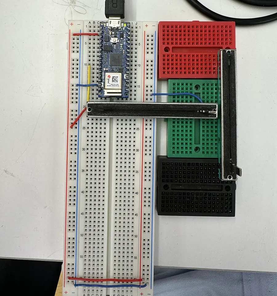
After understanding how to modify value in real time, I ventured to add a sensor for control:
At this point, I started spending more time on the code side, trying to understand how to layer multiple oscillators or what could be done to create more interesting outputs that have more depth. I think a deeper knowledge of how sound synthesis works would be a lot of help. In the end I decided to make one more interactive sketch:
Show/hide code below
#define MOZZI_CONTROL_RATE 128
#include <Mozzi.h>
#include <Oscil.h>
#include <tables/sin2048_int8.h>

//Oscillator for first frequency
Oscil <2048, MOZZI_AUDIO_RATE> aSin(SIN2048_DATA);

//Oscillator for second frequency
Oscil <2048, MOZZI_AUDIO_RATE> aSin2(SIN2048_DATA);

//Oscillator for third frequency
Oscil <2048, MOZZI_AUDIO_RATE> aSin3(SIN2048_DATA);

//Oscillator for fourth frequency
Oscil <2048, MOZZI_AUDIO_RATE> aSin4(SIN2048_DATA);

//Oscillator for vibrato
Oscil <2048, MOZZI_CONTROL_RATE> kVib(SIN2048_DATA);

int freq = 900;
float vibrato = 0;
int combinedOutput = freq;

void setup() {
    startMozzi();
    aSin.setFreq(400);
    aSin2.setFreq(400);
    aSin3.setFreq(400);
    aSin4.setFreq(400);
    kVib.setFreq(6.5f);
}

void updateControl() {
    int trimmerL = mozziAnalogRead<10>(2);
    int trimmerR = mozziAnalogRead<10>(3);

    vibrato = map(constrain(trimmerR, 0 , 1024), 0, 1024, 2, 60) * kVib.next();
    freq = map(constrain(trimmerL, 0 , 1024), 0, 1024, 300, 10000);
    aSin.setFreq(freq + vibrato / 2);
    aSin2.setFreq(freq + 100 + vibrato);
    aSin3.setFreq(freq + 200 + vibrato);
    aSin4.setFreq(freq + 300 + vibrato);
}

AudioOutput updateAudio() {
    combinedOutput = aSin.next() + aSin2.next() + aSin3.next() + aSin4.next(); // Mix the audio signals
    return MonoOutput::from8Bit((combinedOutput / 4)); // Normalize output
}

void loop() {
    audioHook();
}
Week 02
This week we delved into inputs and outputs as well as serial communication. During class, Prof. Rozin recommended that students with previous knowledge in pcomp work beyond the labs to continue their learning.
Therefore, I decided to develop a small project based on the USB capabilities of the nano to simulate a mouse and keyboard. I wanted to create a grid-like interface to control the mouse, setting the x & y of the mouse with sliders. This would allow me to practice using analog sensors and learn more of the mouse functions.
At this point, I realized I had fundamentally misunderstood the Mouse.move() function. I thought that it would allow me to move the mouse to specific coordinates on the screen. Instead, it can just move the mouse relative to its previous position.
This makes a lot of sense given how computer mice work. However, for me it was a big problem.
With a lot of frustration, I figured out I needed to calm down. So I changed my small project to something that could calm me down: A slow breathing visualizer.
The idea was to make a visual representation of my breath, guiding me through slow breathing excercises and relaxation:
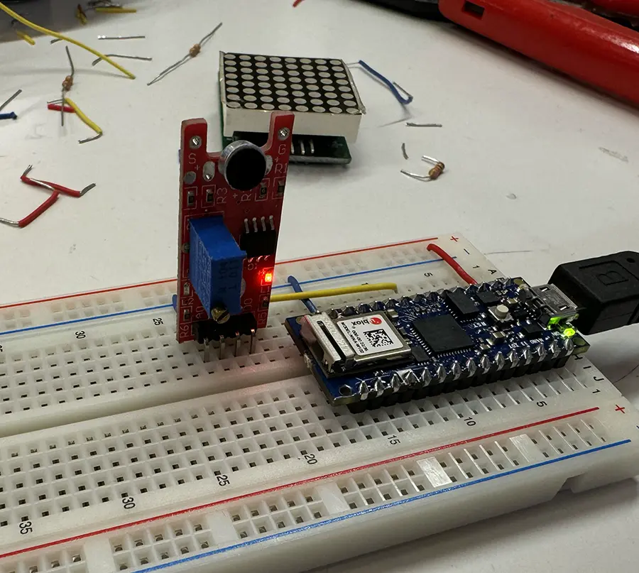
Because the sound sensor was such a cheap low quality component, the signal it gave was really noisey:
In order to clean it up and process it, I remembered a running average filter function I once used, created by researcher Mads Hobye and documented in his doctoral thesis. I applied it to the sensor readings (along with a few other lines to remove the "wave" behavior from the values).
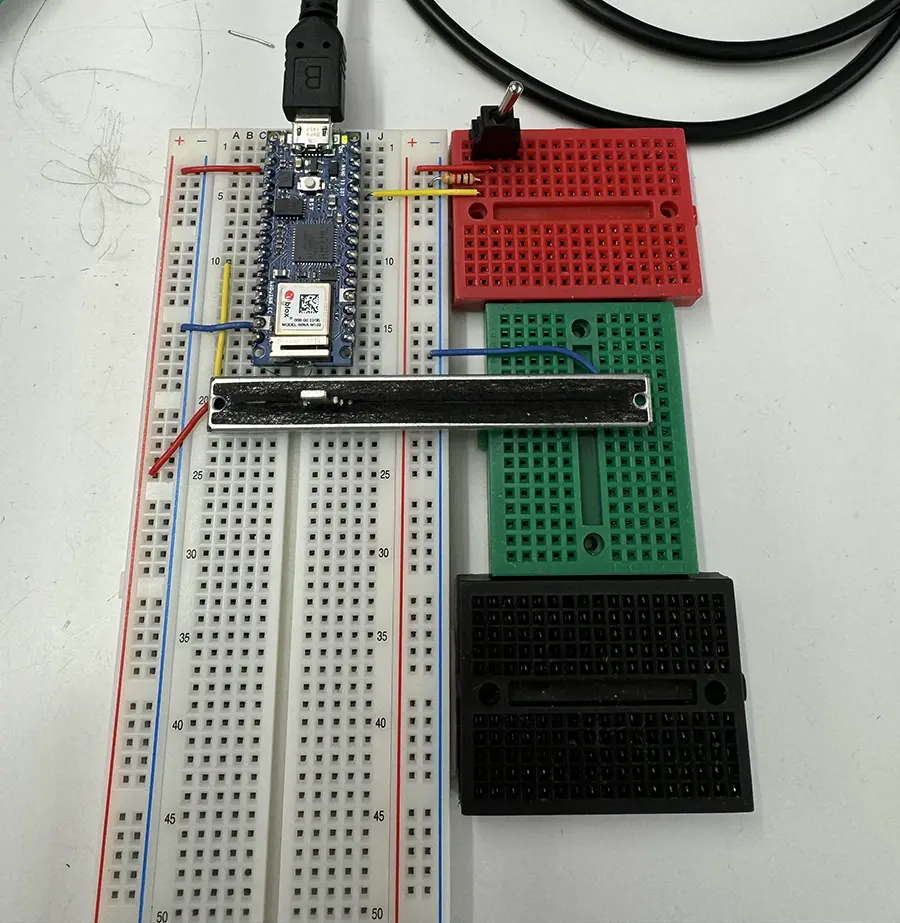
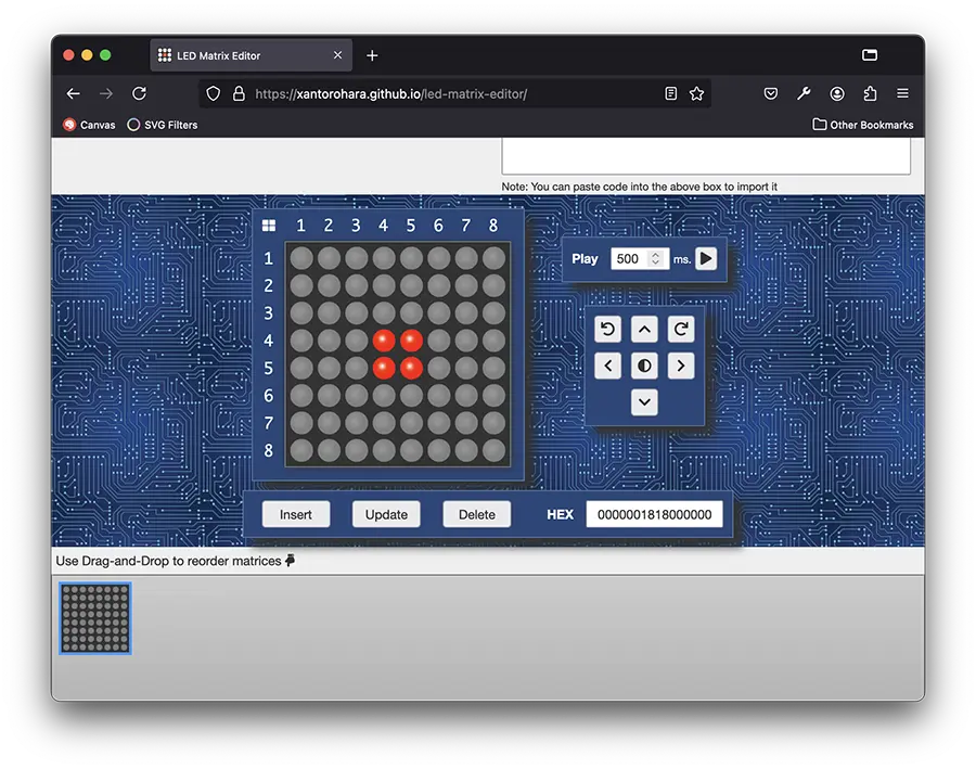
With the sensing out of the way, I needed to work on the actuation. I connected an old led matrix that would be used to visualize my breathing. To control it I used the MAX7219 Library.
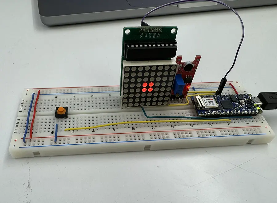
After finishing the code, my visualizer was done:
And this was my final code. A little bit messy but it worked well for a prototype:
Show/hide code below
/*
    September 15-16 2024
    Nasif Rincón

    Relaxing breath visualizer
    A simple device that senses breath as sound and
    visualizes the depth of the breath by filling out
    an LED matrix screen.
*/

#include <MAX7219.h>
//Library: https://github.com/michaelkubina/Arduino_MAX7219_LED_Matrix_Library

//LED Matrix Variables
#define DATAPIN     18
#define CLOCKPIN    19
#define CSPIN       11

MAX7219 Matrix(1, DATAPIN, CLOCKPIN, CSPIN);

//Breath sensor variables
int raw = 0;
float filtered = 0;
int baseline = 520;

void setup() {
    Serial.begin(9600);
    pinMode(A3, INPUT);
    pinMode(5, INPUT_PULLUP);
    Matrix.clearDisplay(1);

    Matrix.setLed(1, 3, 3, true);
    Matrix.setLed(1, 4, 3, true);
    Matrix.setLed(1, 3, 4, true);
    Matrix.setLed(1, 4, 4, true);
}

void loop() {

    if (!digitalRead(5) == HIGH) {
        baseline = analogRead(A3);
        return;
    }

    raw = abs( baseline - analogRead(A3) );
    //Filtering based on the work of Mads Hobye http://www.diva-portal.org/smash/get/diva2:1404339/FULLTEXT01.pdf#page=195
    filtered = filtered * 0.999 + raw * 0.001;

    //Animation
    Matrix.clearDisplay(1);

    if ( filtered > 3 ) {
      levelFive();
    } else if ( filtered > 2.5 ) {
      levelFour();
    } else if ( filtered > 2 ) {
      levelThree();
    } else if ( filtered > 1.5 ) {
      levelTwo();
    } else if ( filtered > 1 ) {
      levelOne();
    } else {
      levelZero();
    }

    //Intensity
    Matrix.setIntensity(1, constrain(filtered, 1, 15) * 2 );
}

void levelZero() {
    Matrix.setLed(1, 3, 3, true);
    Matrix.setLed(1, 4, 3, true);
    Matrix.setLed(1, 3, 4, true);
    Matrix.setLed(1, 4, 4, true);
}

void levelOne() {
    for ( int row = 2; row < 6; row++ ) {
        for ( int col = 2; col < 6; col++ ) {
            if ( (col == 2 && row == 2) || (col == 5 && row == 2) || (col == 5 && row == 5) || (col == 2 && row == 5) ) {
                continue;
            }
            Matrix.setLed(1, row, col, true);
        }
    }
}

void levelTwo() {
    for ( int row = 1; row < 7; row++ ) {
        for ( int col = 1; col < 7; col++ ) {
            if ( (col == 1 && row == 1) || (col == 2 && row == 1) || (col == 5 && row == 1) || (col == 6 && row == 1) ||
                (col == 1 && row == 6) || (col == 2 && row == 6) || (col == 5 && row == 6) || (col == 6 && row == 6) ||
                (col == 1 && row == 2) || (col == 6 && row == 2) ||
                (col == 1 && row == 5) || (col == 6 && row == 5) ) {
                continue;
            }
            Matrix.setLed(1, row, col, true);
        }
    }
}


void levelThree() {
    for ( int row = 0; row < 8; row++ ) {
        for ( int col = 0; col < 8; col++ ) {
            if ( (col == 0 && row == 0) || (col == 1 && row == 0) || (col == 2 && row == 0) || (col == 5 && row == 0) || (col == 6 && row == 0) || (col == 7 && row == 0) ||
                (col == 0 && row == 1) || (col == 1 && row == 1) || (col == 6 && row == 1) || (col == 7 && row == 1) ||
                (col == 0 && row == 2) || (col == 7 && row == 2) ||
                (col == 0 && row == 5) || (col == 7 && row == 5) ||
                (col == 0 && row == 6) || (col == 1 && row == 6) || (col == 6 && row == 6) || (col == 7 && row == 6) ||
                (col == 0 && row == 7) || (col == 1 && row == 7) || (col == 2 && row == 7) || (col == 5 && row == 7) || (col == 6 && row == 7) || (col == 7 && row == 7) ) {
                continue;
            }
            Matrix.setLed(1, row, col, true);
        }
    }
}

void levelFour() {
    for ( int row = 0; row < 8; row++ ) {
        for ( int col = 0; col < 8; col++ ) {
            if ( (col == 0 && row == 0) || (col == 1 && row == 0) || (col == 6 && row == 0) || (col == 7 && row == 0) ||
                (col == 0 && row == 1) || (col == 7 && row == 1) ||
                (col == 0 && row == 6) || (col == 7 && row == 6) ||
                (col == 0 && row == 7) || (col == 1 && row == 7) || (col == 6 && row == 7) || (col == 7 && row == 7) ) {
                continue;
            }
            Matrix.setLed(1, row, col, true);
        }
    }
}

void levelFive() {
    for ( int row = 0; row < 8; row++ ) {
        for ( int col = 0; col < 8; col++ ) {
            Matrix.setLed(1, row, col, true);
        }
    }
}
Week 01
This first week was a refresher on the basic knowledge of electronics, through the development of some short practical labs and technical texts.
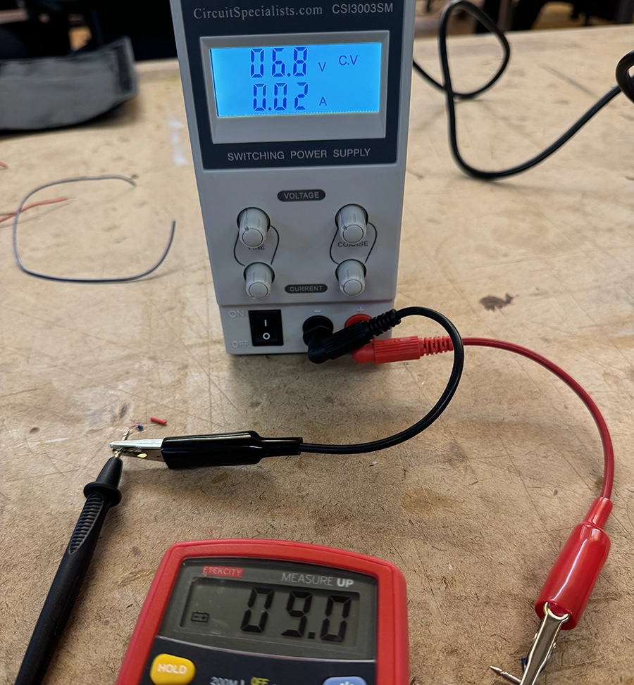
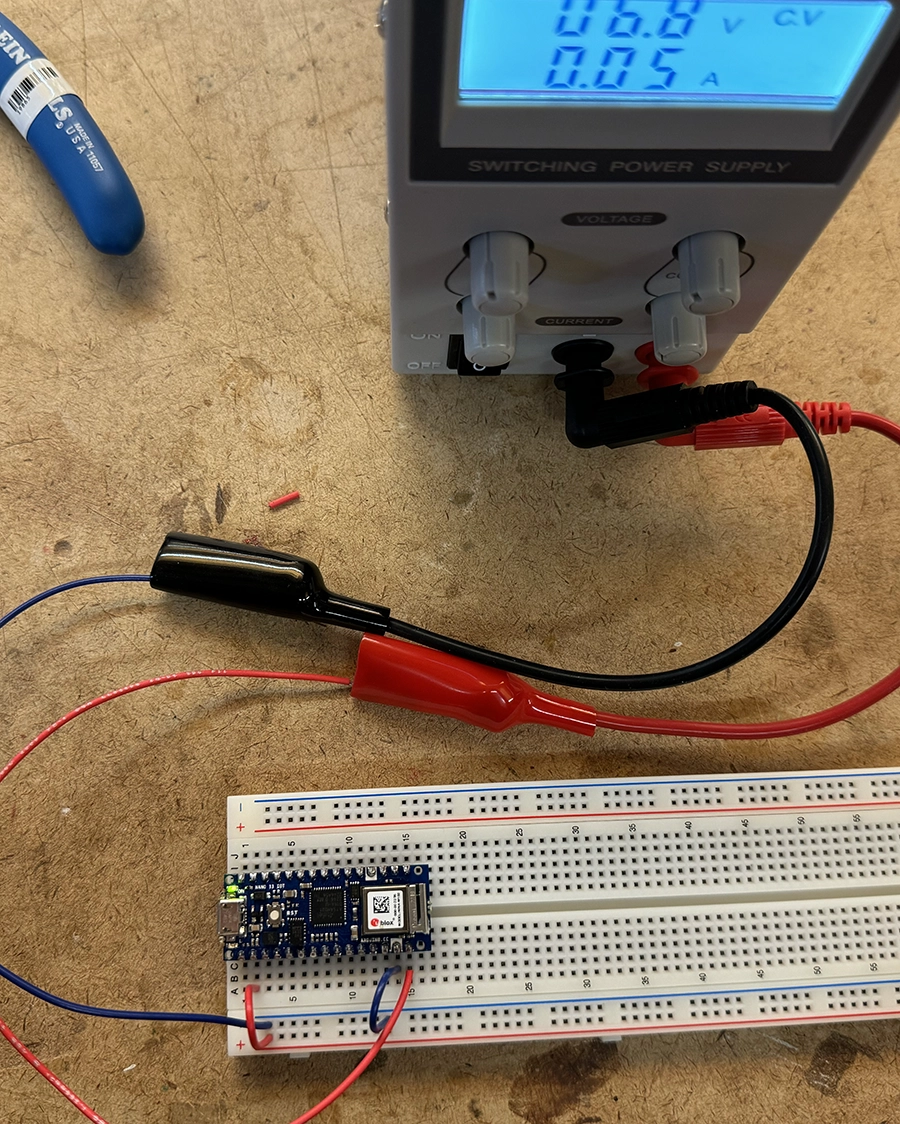
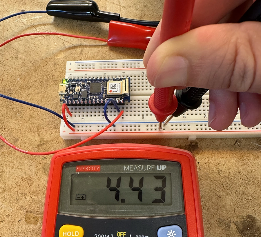
Apart from those labs, I also measured the output voltage from an LM7805 when supplied power from the variable supply. The reading was once again very strange, which corroborated my suspicions that I must be misunderstanding something about the variable supply. I decided to switch to a standard supply for the next lab.
This fade out reminded me of Maywa Denki's machines, some of which have lights that power on instantly with the beats of his music, and then fade away. I decided then to make my switch music-related.
The idea was to make a simple switch that turns on the light to the rhythm of your feet tapping, an action usually done semi-subconsciously when you connect with the music.
After testing it out, I noticed it was very hard to create a connection when tapping, so I iterated:
Then the final switch was ready:
It could definitely benefit from a debounce algorithm on the switch press detection, but I was satisfied with the result considering it was an analog circuit :).